The occurrence of bulk engines is explained by the need to create an electric machine with many advantages. The uncoolette engine is a device without a collector, the function of which takes over the electronics.
BKEPT - Badcontorous electric motors direct currentmay be power, example, 12, 30 volts.
- Choosing a suitable engine
- Principle of operation
- BKEPT device
- Sensors and their absence
- No sensor
- The concept of PWM frequency
- ARDUINO system
- Engine fasteners
Choosing a suitable engine
To select an aggregate, it is necessary to compare the principle of operation and features of collective and neclector engines.
From left to right: Collective engine and engine FC 28-12 Unfaming
Collector cost less, but develop a low rotation speed of torque. They operate from direct current, has a small weight and size, available replacement for the replacement of parts. The manifestation of negative quality is detected upon receipt of a huge number of revolutions. Brushes are in contact with the collector, causing friction, which can damage the mechanism. The efficiency of the unit is reduced.
Brospheres not only require repair due to rapid wear, but also can lead to overheating of the mechanism.
The main advantage of the DC necolettor motor is the incidence of torque and switching contacts. Therefore, the lack of sources of losses, as in the engines with permanent magnets. Their functions perform MOS transistors. Previously, their cost was high, so they were not available. Today the price has become acceptable, and the indicators have improved significantly. In the absence of a radiator in the system, the power is limited from 2.5 to 4 watts, and a current current from 10 to 30 amps. The efficiency of uncoolette electric motors is very high.
The second advantage is the settings of mechanics. The axis is installed on broad-lived. There are no breaking and erasing elements in the structure.
The only minus is dear the electronic unit Control.

Consider the example of CNC mechanics with a spindle.
Replacement of the collector engine on the neclector will protect the spindle breakdown for the CNC. Under the spindle is available in a blow, with the right and left turns of torque. The spindle for CNC has a high power. The torque velocity is controlled by the servotor regulator, and the turnover is controlled by the automatic controller. The cost of CNC with spindle about 4 thousand rubles.
Principle of operation
The main feature of the mechanism is the absence of a collector. BUT permanent magnets Installed from the spindle is a rotor. Around it there are wire windings that have different magnetic fields. Differences of the brushless motors of 12 volts is the rotor control sensor located on it. Signals are fed to the speed controller.
BKEPT device
The magnet location circuit inside the stator is usually used for two-phase engines with a small amount of poles. The principle of torque around the stator is used if necessary to get two-phase engine with minor turns.
 On the rotor are four poles. The magnets in the form of a rectangle are installed, alternating poles. However, not always the number of poles is equal to the number of magnets, which can be 12, 14. But the number of poles must be even. There can be one pole.
The picture shows 8 magnets forming 4 poles. The moment of power depends on the power of magnets.
Sensors and their absence
Travel regulators are divided into two groups: with the rotor position sensor and without.
Current forces are fed to the engine winding at a special position of the rotor. It determines electronic system Using the position sensor. They are a variety of types. Popular stroke control - discrete sensor with hall effect. In the engine for three phases by 30 volts, 3 sensors will be used. The electronics unit constantly has data on the position of the rotor and directs the voltage on time to the necessary windings.
 Common device changing their conclusions when switching windings.
The device with open circuits measures the current, the speed of rotation. PWM channels are attached to the bottom of the control system.
Three inputs are attached to the hall sensor. In case of changing the Hall sensor, the process of processing the interrupt begins. To ensure quick response to the interrupt processing, the Hall sensor is connected to younger port conclusions.

Use the position sensor with a microcontroller
To save money for electricity payments, our readers advise "Energy Economy Electricity Saving Box". Monthly payments will become 30-50% less than before the use of the economy. It removes the reactive component from the network, as a result of which the load is reduced and, as a result, consumption current. Electrical appliances consume less electricity, the costs of its payment are reduced.

The cascade force controller underlies the AVR kernel, which provides competent control of the DC neclector motor. AVR is a chip for performing certain tasks.
The principle of operation of the stroke regulator can be with a sensor and without. The AVR board program implements:
- start of the engine as quickly without using external additional devices;
- speed \u200b\u200bcontrol with one external potentiometer.

Private view automatic control SMA, used in washing machines.
No sensor
 To determine the position of the rotor, it is necessary to measure the voltage to the unused winding. This method is applicable when rotating the engine, otherwise it will not act.
Dummy stroke regulators are made easier, it explains their widespread.
Controllers possess the following properties:
- the value of the maximum DC;
- the value of the maximum operating voltage;
- the number of maximum revolutions;
- resistance of strength keys;
- pulse frequency.
When connecting the controller, it is important to make wires as shorter. Due to the occurrence of currents at the start. If the wire is long, then the errors of the rotor position determination may occur. Therefore, controllers are sold with a wire 12 - 16 cm.
Controllers have a multitude of software settings:
- monitoring the engine shutdown;
- smooth or hard shutdown;
- braking and smooth shutdown;
- capance of power and efficiency;
- soft, hard, fast start;
- current limitations;
- gas mode;
- change direction.

The LB11880 controller shown in the figure comprises a driver of a unkless motor of a powerful load, that is, you can start the engine directly to the chip without additional drivers.
The concept of PWM frequency
When the keys turn on, the full load is supplied to the engine. The unit reaches maximum revolutions. In order to control the engine, you need to provide the power regulator. This is exactly what makes latitude-pulse modulation (PWM).
Install the required opening frequency and closing keys. The voltage varies from zero to working. To control the turns, you must apply a PWM signal to key signals.

The PWM signal can be formed by a device for several conclusions. Or create a PWM for a separate key program. The scheme is becoming easier. PWM signal has 4-80 kilohertz.
An increase in frequency leads to more transition processes, which gives heat release. The height of the PWM frequency increases the number of transient processes, the losses on the keys occur. Small frequency does not give the desired smooth control.
To reduce the losses on the keys in transition processes, the PWM signals are fed to the upper or lower keys separately. Straight losses are calculated by the formula P \u003d R * I2, where P is the power of the loss, R is the key resistance, I is the current strength.
Less resistance minimize losses, increases efficiency.
ARDUINO system
Often, the Arduino hardware computing platform is used to control the architector engines. There is a board and development environment in the Wiring language.
The Arduino fee includes an ATMEL AVR microcontroller and elementalizing programming and interaction with schemes. The board has a voltage stabilizer. Serial Arduino is a simple inverting scheme for converting signals from one level to another. Programs are installed via USB. In some models, for example, Arduino Mini, an additional programming board is required.
Arduino programming language is used standard Processing. Some ARDUINO models allow you to manage multiple servers at the same time. The programs processes the processor, and compiles AVR.
Problems with the controller may occur due to voltage failures and excessive load.
Engine fasteners

Motor-engine mounting mechanism. Used in engine installations. Motor is interrelated rods and framework elements. Motors are flat, spatial in elements. Motor of a single engine of 30 volts or multiple devices. The power scheme of the motor consists of a totality of rods. Motor is installed in a combination of fermented and frame elements.
Badcontator DC electric motor is an indispensable unit used both in everyday life and in industry. For example, CNC machine, medical equipment, automotive mechanisms.
BKEPT is allocated reliable, high-precision principle of work, automatic intellectual control and regulation.
This variety of an AC motor, which has a collector-brush node is replaced by a contactless semiconductor switch, controlled by the rotor position sensor. Sometimes you can meet such an abbreviation: BLDC is Brushless DC Motor. For simplicity, I will call it an insane engine or simply BC.
Badzolettor engines are quite popular due to its specifics: no consumables The type of brushes, there is no coal / metal dust inside friction, there are no sparks (and this is a huge direction of explosive and fire of safe drives / pumps). Used from fans and pumps ending with high-precision drives.
Basic use in models and amateur structures: engines for radio-controlled models.
The general meaning of these engines is the three phases and three windings (or several windings connected to three groups) controlled by the signal in the form of sinusoids or approximate sinusoids for each of the phases, but with some shift. In the picture, the simplest illustration of the three-phase engine work.
Accordingly, one of the specific points of control of the BC engines is the use of a special drivers controller, which allows you to adjust current pulses and voltage for each phase on the engine windings, which ultimately gives stable work In a wide range of stresses. These are the so-called ESC controllers.
BK Motors for R / in technology There are various sizes and execution. Some of the most powerful series are 22 mm, 36 mm and 40/42 mm. By design, they are with an external rotor and internal (Outrunner, Inrunner). Motors with an external rotor in fact do not have a static housing (shirts) and are lightweight. As a rule, used in aircraft model, in quadrochopters, etc.
Engines with an external stator easier to make hermetic. Similar are used for p / in models that are exposed to external influences type of dirt, dust, moisture: buggie, monsters, cranes, water p / at the model).
For example, the engine type 3660 can be easily set in the r / y model of a car such as a buggy or monster and get a lot of pleasure.
I also note the various layout of the stator itself: the 3660 engines have 12 coils connected to three groups.
This allows you to get a high moment on the shaft. It looks like this. 
Connected coils like this 
If you disassemble the engine and remove the rotor, you can see the coil of the stator.
That's what is inside 3660 series 
more photos 
Amateur use of similar engines with a high point - in homemade structureswhere a small-sized powerful turn engine is required. These can be turbine type fans, amateur spindles, etc.
So, with the goal of installing in an amateur machine for drilling and engraving, a set of an uncoolette engine was taken together with the ESC controller
Goolrc 3660 3800KV Brushless Motor WITH ESC 60A Metal Gear Servo 9.0kg Set
The plus in the set was a servo for 9 kg, which is very convenient for homemade.
General requirements when choosing a motor was as follows:
- The number of revolutions / volts is at least 2000, as it was planned to use with low-voltage sources (7.4 ... 12V).
- shaft diameter 5mm. Considered the options with a shaft of 3.175 mm (this is a series of 24 diameters of engines BC, for example, 2435), but then I would have to buy a new cartridge ER11. There are options even more powerful, for example, 4275 or 4076 engines, with a 5 mm shaft, but they are more expensive, respectively.
Characteristics of the Boltor Motor Goolrc 3660:
Model: Goolrc 3660
Power: 1200w
Operating voltage: up to 13V
Local current: 92A
Volt Turnover (RPM / VOLT): 3800KV
Maximum turnover: up to 50000
Case diameter: 36mm
Case Length: 60mm
Shaft length: 17mm
Shaft diameter: 5mm
Installation screw size: 6 pcs * M3 (short, I used m3 * 6)
Connectors: 4mm Gold Plated "Bananas" Male
Protection: from dust and moisture
ESC Characteristics Controller:
Model: Goolrc ESC 60A
Long current: 60A
Peak current: 320A
Applied rechargeable batteries: 2-3s Li-PO / 4-9S Ni-MH Ni-CD
Bec: 5.8V / 3A
Connectors (Login): T Plug Male
Connectors (Age.): 4mm Gold Plated "Bananas" female
Dimensions: 50 x 35 x 34mm (excluding cable length)
Protection: from dust and moisture
Characteristics of the servo:
Operating voltage: 6.0V-7.2V
Rotation speed (6.0V): 0.16SEC / 60 ° without load
Rotation speed (7.2V): 0.14SEC / 60 ° without load
Moment Hold (6.0V): 9.0kg.cm
Moment Hold (7.2V): 10.0kg.cm
Dimensions: 55 x 20 x 38mm (d * sh * c)
Set parameters:
Package size: 10.5 x 8 x 6 cm
Packing Mass: 390 gr
Branded packaging with Goolrc logo
Complete composition:
1 * Goolrc 3660 3800KV Motor
1 * Goolrc 60a ESC
1 * Goolrc 9kg Servo
1 * Information sheet 
Sizes for reference and appearance Goolrc 3660 engine indicating the main points 
Now a few words about the premise itself.
The parcel came in the form of a small mail package with a box inside 
Delivered by an alternative postal service, not by mail of Russia, what and says the transport invoice 
In the parcel, branded box Goolrc 
Inside the kit of the base-sensitive engine size 3660 (36x60 mm), the ESC controller for it and the servo with a set 
Now consider the entire set of separate components. Let's start with the most important thing - from the engine.
BC Engine Goolrc is an aluminum cylinder, sizes 36 to 60 mm. On the one hand, three thick wires in silicone braid with "bananas" come out, on the other hand shaft 5 mm. The rotor from two sides is mounted on rolling bearings. On the case there is a model marking 
Another photo. Exterior shirt fixed, i.e. Engine Type Inrunner. 
Marking on the housing 
From the rear end you can see the bearing 
Defined protection against splashes and moisture
Three thick, short wires for connecting phases: u v w. If you search for terminals for connectivity - these are bananas of 4 mm 
Wires have a heat shrink different color: Yellow, Orange and Blue 
Motor dimensions: diameter and shaft length coincide with the stated: shaft 5x17 mm 

Engine housing dimensions 36x60 mm 

Comparison with collector 775 engine 
Comparison with used spindle on 300W (and at the cost of about $ 100). I remind you that the Goolrc 3660 decides the peak power of 1200W. Even if you use a third of the power, it is still cheaper and more than that spindle 
Comparison with other model engines 
For the correct operation of the engine will require a special ESC controller (which is included)
ESC Controller is the engine driver board with a signal converter and powerful keys. On the simple models Instead of the housing, a heat shrinkage is used, on powerful - the case with the radiator and active cooling. 
In the photo, the Goolrc ESC 60A controller compared to the "younger" brother ESC 20A 
Please note: There is a shutdown shutdown toggle on a wire segment that can be embedded in the device / toys 
There is a complete set of connectors: Input T connectors, 4 mm Banana-sockets, 3-pin input control signal 
Power bananas are 4 mm - nests, marked similarly by colors: yellow, orange and blue. When connected, you can only intentionally 
Input T-connectors. Similarly, you can confuse polarity if you are very strong))))) 
On the case there is a marking with the name and characteristics, which is very convenient 
Cooling is active, works and regulated automatically.
PCB Ruller applied for sizes 
The set also presents the Goolrc servo on 9 kg. 
Plus, as for any other servo in the kit there is a set of levers (double, cross, star, wheel) and fastening fittings (liked that there are places from brass) 
Macrofoto Shal Servomashki 
We try to fix the cruciform lever for the photo 
In fact, it is interesting to check the claimed savings - this is a metal set of gears inside. We disassemble the servo. The body sits on sealant in a circle, and inside there is a rich lubricant. The gears and the truth is metallic. 
Stock Foto Paper control board 
For which it all was stood: in order to try the BC engine as a floring / engraving. All the same, the peak power is 1200W.
I chose a drilling machine project to prepare printed circuit boards on. There are many projects for the manufacture of a luminament desktop. As a rule, all these projects are small-sized and are designed to install a small DC motor. 
I chose one of and finalized the mount in the part of the engine holders 3660 (the native engine was less and had other fasteners)
I give drawing seating and engine dimensions 3660 
In the original cost more weak Engine. Here is the sketch of the mount (6 holes for M3x6) 
Screen from Printer Print Program 
At the same time printed and clamp for fastening from above 
Motor 3660 with Cancel Cartridge type ER11 

To connect and verify the motor BC, you will need to collect the following scheme: power supply, servotester, or control board, ESC controller engine, engine.
I use the simplest servotester, it also gives the desired signal. It can be used to turn on and for adjusting the engine speed. 
If you wish, you can connect a microcontroller (Arduino, etc.). I cite a scheme from the Internet with an autoinner connection and 30A controller. Sketches find no problem. 
We connect everything in colors. 
The source shows that idle of the controller is small (0.26a) 
Now the drilling machine.
We collect everything and krepim on the rack 

To check, collect without the case, then preparing the case where you can install the standard switch, the servotester twist 
Another use of a similar 3660 engine BC - as spindle machines for drilling and milling of printed circuit boards 


About the Overview Machine Immediately later. It will be interesting to check the engraving of printed circuit boards using Goolrc 3660
Conclusion
The engine is high-quality, powerful, torque with a margin is suitable for amateur objects.
Specifically, the vitality of bearings with lateral effort during milling / engraving will show time.
There is definitely the benefit of the use of model engines as far as possible, as well as the simplicity of work and assembly of structures on them compared to CNC spindles, which are more expensive and require special equipment (power sources with revolutions, drivers, cooling, etc.).
When ordering used a coupon Sale15 With a discount of 5% on all store products.
Thanks for attention!
I plan to buy +61 Add to favourites I liked the review +92 +156The engines in multi-motor vehicles are of two types: collector and neclector. Their main difference is that the collector engine windings are located on the rotor (rotating part), and in the neclector - in the stator. Without going into details, let's say that the baseball engine is preferable to collector since most satisfies the requirements put in front of it. Therefore, this article will be discussed in this type of engines. In detail about the difference between the baseball and collector engines, you can read in.
Despite the fact that the BC-motors began to be applied relatively recently, the very idea of \u200b\u200btheir device appeared for a long time. However, the emergence of transistor keys and powerful neodymium magnets made it possible to commercial use.
BC device - motors
The design of the uncoolette engine consists of a rotor on which the magnets and the stator are fixed on which windings are located. Just by interpretation of these components, BC engines are divided into Inrunner and Outrunner.
In multi-engine systems, the OutRunner scheme is more often used, since it allows you to get the greatest rotational moment.
Pros and Cons BC - Engines
Pros:
- Simplified motor design by exclusion from her collector.
- Higher efficiency.
- Good cooling
- BC engines can work in water! However, do not forget that because of the water on mechanical parts The engine can form rust and it will break after a while. To avoid such situations, it is recommended to handle engines with water repellent lubrication.
- The smallest radiopomehi
Minuses:
Of the minuses, it is possible to note only the impossibility of using these engines without ESC (rotational speed controllers). This somewhat complicates the design and makes the BC engines more expensive collector. However, if the complexity of the design is a priority parameter, then there are BC engines with built-in speed controllers.
How to choose engines for a copter?
When choosing neclector engines, first of all, attention should be paid to the following characteristics:
- Maximum current - this characteristic shows which maximum current can withstand the engine winding over a short period of time. If you exceed this time, the engine outlet is inevitable. Also, this parameter affects the choice of ESC.
- Maximum voltage - as well as the maximum current, shows which voltage can be submitted for a short period of time.
- KV - the number of engine speeds per volt. Since this indicator directly depends on the load on the motor shaft, it is indicated for the case when there is no load.
- Resistance - depends on resistance Efficiency engine. Therefore, the resistance is less - the better.
In this article, we would like to tell about how we have created an electric motor from scratch: from the appearance of the idea and the first prototype to a full-fledged motor who has passed all the tests. If this article will seem interesting to you, we are separately detailed, we will tell about the most interested stages of our work.
On the picture from left to right: rotor, stator, partial assembly of motor, motor assembly
Introduction
Electrical motors appeared more than 150 years ago, but during this time their design has not undergone special changes: a rotating rotor, copper stator windings, bearings. Over the years, there has been only a decrease in the weight of electric motors, an increase in efficiency, as well as accuracy of speed control.Today, thanks to the development of modern electronics and the emergence of powerful magnets based on rare earth metals, it is possible to create more than ever, and at the same time compact and light "neclector" electromotors. At the same time, due to the simplicity of its design, they are most reliable among ever created electric motors. About creating such a motor and will be discussed in this article.
Motor Description
In "Badcontor Motors" there is no familiar element "Brushes", the role of which is the role of which lies in the transmission of current to winding the rotating rotor. In the brushless engines, the current is fed to the winding of a non-moving stator, which, creating a magnetic field alternately on separate poles, spins the rotor on which magnets are fixed.The first such motor was printed by us 3D printer as an experiment. Instead of special plates of electrical steel, for the rotor body and the core of the stator, to which the copper coil was wound, we used the usual plastic. Neodymium rectangular neodymium magnets were fixed on the rotor. Naturally, such a motor was not capable of issuing maximum power. However, this was enough that the motor would spin up to 20K RPM, after which the plastic could not stand and the rotor of the motor was ripped, and the magnets cried around. This experiment is advised us to create a full-fledged motor.
The few first prototypes
Having learned the opinion of lovers of radio-controlled models, as a task, we chose a motor for the 540 size racing machinery, as the most sought-after. This motor has dimensions of 54mm in length and 36mm in diameter.
The rotor of the new motor, we made from a single neodymium magnet in the form of a cylinder. The epoxy magnet was glued to the shaft sharpened from instrumental steel on the experimental production.

The stator we cut out a laser from a set of transformer plates with a thickness of 0.5mm. Each plate was then thoroughly covered with varnish and then the finished stator was glued out of about 50 plates. Laco plates were covered in order to avoid closure between them and eliminate energy loss on Foucault currents that could arise in the stator.

The motor housing was made of two aluminum parts in the form of a container. The stator is tight in the aluminum case and adjacent to the walls. Such a design provides good cooling Motor.

Characteristic measurement
For achievement maximum characteristics Its developments, it is necessary to conduct an adequate assessment and accurate measurement of characteristics. For this, we have been designed and assembled a special dinostite.
The main element of the stand is a heavy cargo in the form of a washer. During the measurements, the motor spins this load and the output power and moment of the motor are calculated along the angular velocity and acceleration.
To measure the speed of cargo rotation, uses a pair of magnets on the shaft and the magnetic digital sensor A3144 based on the Hall effect. Of course, it would be possible to measure the speed of pulses directly from the winding of the motor, since this motor is synchronous. However, the option with the sensor is more reliable and it will work even on very small revolutions, on which the pulses will be unreadable.
In addition to revolutions, our booth is able to measure several more important parameters:
- power current (up to 30a) using a current sensor based on the ACS712 Hall Effect;
- supply voltage. It is measured directly through the microcontroller ADC, through the voltage divider;
- the temperature inside / outside the motor. The temperature is measured by semiconductor thermal resistance;

As a result, our booth can measure the following motor characteristics during an arbitrary moment:
- current consumption;
- voltage consumed;
- power consumption;
- output power;
- shaft turnover;
- moment on the shaft;
- power flowing into heat;
- temperature inside the motor.
Test results
To test the booth's performance, we first experienced it on the usual collector motor R540-6022. The parameters for this motor know quite a little, however, it was enough to evaluate the measurement results that were close enough to the factory.Then, our motor was already tested. Naturally, he was able to show the best efficiency (65% against 45%) and at the same time a larger point (1200 versus 250 g per cm) than the usual motor. Temperature measurement also made enough nice results, During testing, the motor did not heat up 80 degrees.
But at the moment the measurement is not yet final. We could not measure the motor in the full range of revolutions due to the power supply limit. It will also be necessary to compare our engine with similar motors of competitors and test it "in battle", putting on racing radio-controlled machine And perform at competitions.
Distinctive features:
- BCEPT General Information
- Uses the power cascade controller
- Sample program code
Introduction
This application guidelines are described in these application recommendations, how to implement a control unit for controlling the DC control motor (BKEPT) using a position sensor based on AVR microcontroller AT90PWM3.
The high-performance microcontroller AVR core, which contains a power cascade controller, allows you to implement a controller for controlling a high-speed DC controller motor.
This document provides a short description of the principle of operation of the uniform electric motor of the DC, and in the details there is a BCEPT control in touch mode, and also describes the description concept The ATAVRMC100 reference development, which is based on these Application Recommendations.
Also discussed software implementation with a software-implemented control circuit based on the PID controller. To control the switching process, the use of only position sensors based on the Hall effect is implied.
Operating principle
The scope of BKEPT continuously increases, which is associated with a number of their advantages:
- The absence of a collector node, which simplifies or even excludes maintenance.
- Generation more low level Acoustic and electrical noise compared to universal manifold DC motors.
- Ability to work in hazardous environments (with flammable products).
- Good ratio of bulb characteristics and power ...
Engines of this type are characterized by a small inertia of the rotor, because Winding are located on the stator. Switching is controlled by electronics. Moments of switching are defined either according to information from position sensors, or by measuring the reverse e.d., generated by windings.
When operating using BKEPT sensors, it is usually of the three main parts: a stator, a rotor and linel sensors.
The stator of the classic three-phase BKEPT contains three windings. In many engines, the windings are divided into several sections, which reduces the rolling moment pulsations.
Figure 1 shows electrical circuit Substitution of the stator. It consists of three windings, each of which contains three consecutive elements included: inductance, resistance and reverse E.D.S.
Figure 1. Electrical stator replacement scheme (three phases, three windings)
The BKEPT rotor consists of an even number of permanent magnets. The amount of magnetic poles in the rotor also affects the size of the rotation and rolling momentum steps. The greater the number of poles, the smaller the size of the rotation step and less rolling momentum. Permanent magnets can be used with 1..5 pairs of poles. In some cases, the number of pairs of poles increases to 8 (Figure 2).

Figure 2. Stator and rotor of three-phase, three-winding BKEPT
The windings are installed stationary, and the magnet rotates. The BKEPT rotor is characterized by a lighter weight relative to the rotor of an ordinary universal DC motor, which is located on the rotor.
Hall Sensor
To estimate the position of the rotor, three Hall sensors are embedded in the engine housing. Sensors are installed at an angle of 120 ° in relation to each other. Using sensor data it is possible to perform 6 different switches.
Switching phases depends on the state of the hall sensors.
The supply of supply voltages on the winding changes after changing the states of the Hall sensor outputs. With the correct execution of synchronized switching, the torque remains approximately constant and high.
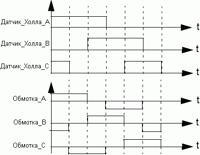
Figure 3. Hall sensor signals in the process of rotation
Switching phases
In order to simplify the description of the work of the three-phase BKEPT, we consider only its version with three windings. As previously shown, the switching phase depends on the output values \u200b\u200bof the Hall sensors. With the correct supply of voltage on the engine winding, a magnetic field is created and rotation is initiated. The most common I. simple way Switch control used to control BKEPT is the turning on-shutdown scheme when the winding either spends the current or not. At one point in time, only two windings can be seized, and the third remains disconnected. Connecting windings to power bus causes electric current. This method is called trapezoidal commutation or block switching.
A power cascade consisting of 3 half-liters is used to control BKEPT. The scheme of the power cascade is shown in Figure 4.

Figure 4. Power Cascade
According to the values \u200b\u200bof the Hall sensors, it is determined which keys must be closed.
Table 1. Switching the keys clockwise
In engines with several fields, electrical rotation does not correspond to mechanical rotation. For example, in four-polyvous BKEPT, four electrical rotation cycles correspond to one mechanical rotation.
The power and speed of the engine depends on the power of the magnetic field. You can adjust the speed of rotation and rotating the engine by changing the current through the winding. The most common way to control the current through the winding is the middle current. To do this, use latitude-pulse modulation (PWM), the operating cycle of which determines the average voltage value on the windings, and, therefore, the average current value and, as a result, the rotational speed. The speed can be adjusted at frequencies from 20 to 60 kHz.
The rotating field of three-phase, three-winding BKEPT is shown in Figure 5.

Figure 5. Switching steps and rotating field
The switching process creates a rotating field. On the stage 1 phase A, it connects to the positive feed bus of the SW1 key, the phase B is connected to a common with the SW4 key, and the phase C remains unconnected. Phases A and B are created two vector magnetic flux (shown in red and blue arrows, respectively), and the sum of these two vectors gives the vector of the magnetic stream of the stator (green arrow). After that, the rotor tries to follow the magnetic stream. As soon as the rotor reaches a certain position in which the state of the hall sensors is changed from the "010" value to "011", the switching of the engine windings is performed accordingly: the phase in remains uncasal, and the phase C is connected to the total. This leads to the generation of the new vector of the magnetic stream of the stator (stage 2).
If you follow the switching scheme shown in Figure 3 and in Table 1, we obtain six different magnetic flux vectors corresponding to six switching steps. Six steps correspond to one rotor turnover.
Starter set atavrmc100
The circuit diagram is presented in Figures 21, 22, 23 and 24 at the end of the document.
The program contains a speed control circuit with a PID controller. Such a regulator consists of three links, each of which is characterized by its own transmission ratio: KP, KI and KD.
KP is the transmission coefficient of the proportional link, Ki is the transmission coefficient of the integrating link and KD - the coefficient of transmission of the differentiating link. The deviation of the specified speed from the actual (in Figure 6 is called the "Missing" signal ") is processed by each of the links. The result of these operations is folded and fed to the engine to obtain the desired speed of rotation (see Figure 6).

Figure 6. Structural PID Regulator Scheme
The CP coefficient affects the duration of the transition process, the coefficient ki allows you to suppress static errors, and the CD is used, in particular, to stabilize the position (see the description of the control circuit in the software archive for changing coefficients).
Description of hardware
As shown in Figure 7, the microcontroller contains 3 power cascade controllers (PSC). Each PSC can be considered as a latitude-pulse modulator (PWM) with two output signals. To avoid the occurrence of through current, the PSC supports the ability to control the latency of the power of power keys (see the documentation for AT90PWM3 for a more detailed study of the PSC operation, as well as Figure 9).
Emergency input (over_current, current overload) is associated with PSCIN. Emergency input allows the microcontroller to disable all PSC outputs.

Figure 7. Hardware implementation
To measure the current, two differential channels with a programmable amplifier cascade can be used (ku \u003d 5, 10, 20 or 40). After selecting the gain coefficient, it is necessary to pick up the nominal sunting resistor for the most complete coverage of the conversion range.
The Over_Current signal is formed by an external comparator. The threshold voltage of the comparator can be adjusted using an internal DAC.
Switching the phases must be performed in accordance with the value at the outputs of the Hall sensors. DH_A, dh_b and dh_c are connected to the inputs of sources of external interrupts or to three internal comparators. Comparators generate the same type of interrupts as external interrupts. Figure 8 shows how the I / O ports are used in the starting set.
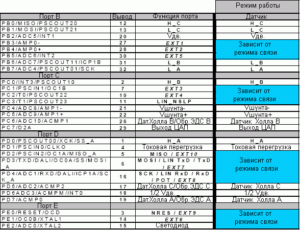
Figure 8. Using the microcontroller I / O ports (SO32 housing)
VMOT (VDV) and VMOT_HALF (1/2 VDV) are implemented, but not used. They can be used to obtain information about the power supply voltage.
Outputs H_x and L_X are used to control the power bridge. As mentioned above, they depend on the power cascade controller (PSC), which generates PWM signals. In this application, it is recommended to use control mode in the center (see Figure 9) when the OCR0RA register is used to synchronize the launch of the ADC transformation to measure the current.

Figure 9. Oscillograms of PSCN0 and PSCN1 signals in level alignment mode
- Time incl. 0 \u003d 2 * OcrNSA * 1 / FCLKPSC
- Time incl. 1 \u003d 2 * (OCRNRB - OCRNSB + 1) * 1 / FCLKPSC
- PSC \u003d 2 * (OCRNRB + 1) * 1 / FCLKPSC
Non-defense pause between PSCN0 and PSCN1:
- | OcrNSB - OcrNSA | * 1 / FCLKPSC
The PSC block is clocked by CLKPSC signals.
One of two methods can be used to feed the PWM signals in the power cascade. The first is the application of the PWM signals to the upper and lower parts of the power cascade, and the second - in the PWM signals application only to the upper parts.
Description software
Atmel has developed libraries to manage BKEPT. The first step of their use is the configuration and initialization of the microcontroller.
Configuration and initialization of the microcontroller
To do this, use the MC_INIT_MOTOR () function. It causes the function of initializing the hardware and software part, as well as initializes all engine parameters (direction of rotation, speed and stop motor).
Software structure structure
After the configuration and initialization of the microcontroller can be launched the engine. Only several functions are needed to control the engine. All functions are defined in MC_LIB.H:
Void MC_MOTOR_RUN (Void) - Used to start the engine. The stabilization circuit function is called to install the PWM working cycle. After that, the first switching phase is performed. BOOL MC_MOTOR_IS_RUNNING (Void) - Determining the engine status. If "1", the engine works if "0", the engine is stopped. Void MC_Motor_Stop (Void) - Used to stop the engine. Void MC_SET_MOTOR_SPEED (U8 SPEED) - installation of a user-defined speed. U8 MC_GET_MOTOR_SPEED (Void) - Returns the user specified speed. Void MC_SET_MOTOR_DIRECTION (U8 Direction) - setting the direction of rotation "CW" (clockwise) or "CCW" (counterclockwise). U8 MC_GET_MOTOR_DIRECTION (Void) - Returns the current direction of rotation of the engine. U8 MC_SET_MOTOR_MEASURED_SPEED (U8 Measured_Speed) - Saving the measured speed in the MEASURED_SPEED variable. U8 MC_GET_MOTOR_MEASURED_SPEED (Void) - Returns the measured speed. void mc_set_close_loop (void) void mc_set_open_loop (void) - stabilization circuit configuration: closed loop or open (see Figure 13).
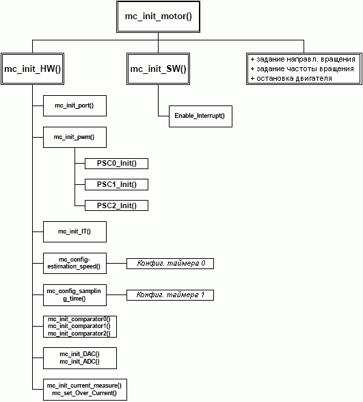
Figure 10. AT90PWM3 configuration
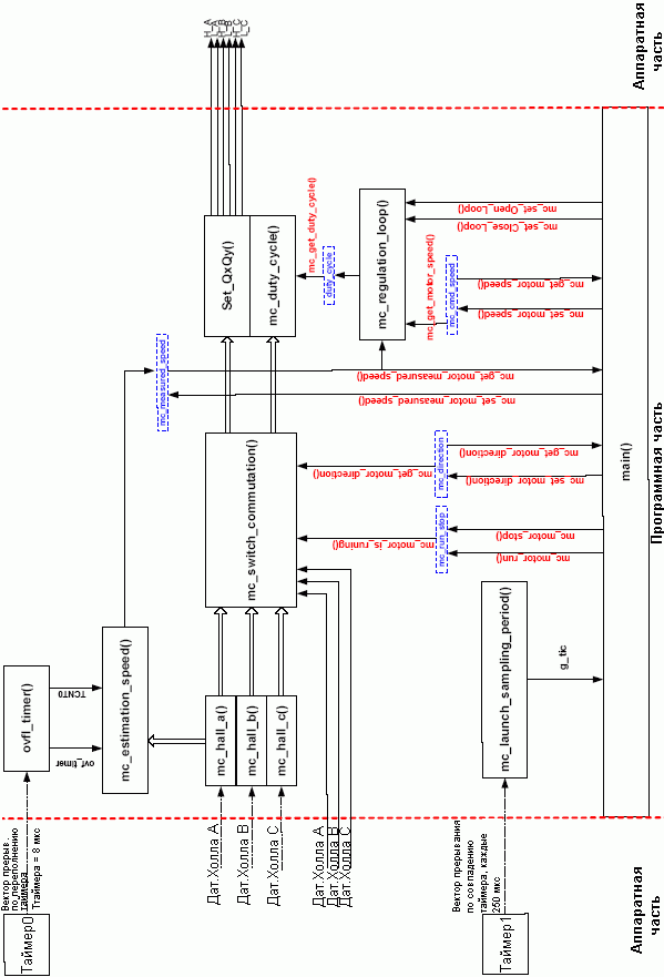
Figure 11. Software structure
Figure 11 shows four variables MC_RUN_STOP (START / STOP), MC_Direction (Direction), MC_CMD_SPEED (specified speed) and MC_MEASURD_SPEED (measured speed). They are the main software variables, access to which can be performed by the previously described user functions.
Software implementation can be viewed as a black box with the name "Engine Management" (Figure 12) and multiple inputs (MC_RUN_STOP, MC_Direction, MC_CMD_SPEED, MC_MEASURD_SPEED) and outputs (all power bridge control signals).
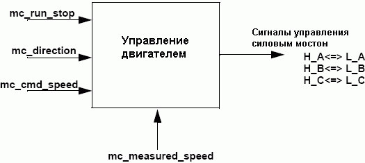
Figure 12. Basic software variables
Most features are available in MC_DRV.H. Only some of them depend on the type of engine. Functions can be divided into four main classes:
- Initialization of the hardware void mc_init_hw (void); The initialization of the hardware is fully implemented in this function. Here are initialized ports, interrupts, timers and controllers of the power cascade.
- Switching functions U8 MC_GET_HALL (Void); Reading the state of the hall sensors corresponding to six switching steps (HS_001, HS_010, HS_011, HS_100, HS_101, HS_110).
Interrupt void MC_HALL_A (Void); _Interrupt void mc_hall_b (void); _Interrupt void mc_hall_c (void); These functions are executed if the external interruption is detected (changing the output of the Hall sensors). They allow you to switch the phases and calculate the speed.
Void MC_DUTY_CYCLE (U8 LEVEL); This function sets the operating cycle of PWM in accordance with the PSC configuration.
Void MC_SWITCH_COMMUTIATION (U8 Position); The switching of the phases is performed in accordance with the value at the outputs of the Hall sensors and only if the user starts the engine.
- Configuration of the Time Conversion Void MC_CONFIG_SAMPLING_PERIOD (Void); Timer 1 initialization for interrupt generation every 250 μs. _interrupt void launch_sampling_period (void); After activating 250 μL interrupts sets the flag. It can be used to control the conversion time.
- Void valuation Void MC_CONFIG_TIME_ESTIMATION_SPEED (Void); Configuration Timer 0 To perform the speed calculation function.
Void MC_ESTIMATION_SPEED (Void); This function calculates the engine speed based on the principle of measuring the period of the liner sensor pulses.
Interrupt void OVFL_TIMER (Void); If an interrupt occurs, an increment of an 8-bit variable is incremented for implementing a 16-bit timer using an 8-bit timer.
- Current measurement _interrupt void ADC_EOC (Void); The ADC_EOC function is performed immediately after converting the amplifier to install the flag that the user can be used.
Void MC_INIT_CURRENT_MEASURE (Void); This feature initializes amplifier 1 for current measurement.
U8 MC_GET_CURRENT (Void); Read current value if the conversion is complete.
BOOL MC_CONVERSION_IS_FINISHED (Void); Indicates conversion completion.
Void mc_ack_eoc (void); Reset the conversion completion flag.
- Detection of current overloading Void MC_SET_OVER_CURRENT (U8 LEVEL); Sets the threshold for determining the current overload. As a threshold, there is an exit of the DAC associated with the external comparator.
Void mc_init_sw (void); Used to initialize software. Allows all interrupts.
Void MC_INIT_PORT (Void); Initialization of the I / O port by setting through the DDRX registers, which conclusions function as an input, and which output, as well as indicating which inputs it is necessary to enable pull-up resistors (through the portx register).
Void mc_init_pwm (void); This feature starts the PLG and sets all PSC registers to its original state.
Void mc_init_it (void); Modify this feature to resolve or prohibit interrupt types.
Void PSC0_INIT (Unsigned int DT0, unsigned int ot0, unsigned int dt1, unsigned int ot1); Void PSC1_INIT (unsigned int dt0, unsigned int ot0, unsigned int dt1, unsigned int ot1); Void PSC2_INIT (unsigned int dt0, unsigned int ot0, unsigned int dt1, unsigned int ot1); PSCX_INIT allows the user to select the configuration of the power cascade controller (PSC) of the microcontroller.
The stabilization circuit is selected using two functions: open (MC_SET_OPEN_LOOP ()) or closed circuit (MC_SET_CLOSE_LOOP ()). Figure 13 shows a software-implemented stabilization circuit.

Figure 13. Stabilization circuit
A closed circuit is a circuit of stabilization of the PID-regulator-based speed.
As shown earlier, the KP coefficient is used to stabilize the engine response time. At first, set the ki and kD equal to 0. To obtain the desired engine response time, you must select the value of the KP.
- If the response time is too small, then increase the CP.
- If the response time is fast, but not stable, then reduce the CP.

Figure 14. Setting up KP
The ki parameter is used to suppress the static error. Leave the CP coefficient unchanged and set the ki parameter.
- If the error differs from zero, then increase the ki.
- If the suppression of the error was preceded by an oscillatory process, then reduce the ki.

Figure 15. Custom
Figures 14 and 15 shows examples of selecting the correct parameters of the KP regulator \u003d 1, ki \u003d 0.5 and kd \u003d 0.
Setting the CD parameter:
- If the speed is low, then increase the CD.
- With instability of the CD, it is necessary to reduce.
Another essential parameter is the conversion time. It must be chosen regarding the system reacting time. The conversion time must be at least two times less than the response time of the system (according to the Cotelnikov rule).
To configure the conversion time, two functions are provided (discussed above).
Their result is displayed in the G_Tick global variable, which is installed every 250 μs. With this variable it is possible to configure the conversion time.
CPU and memory usage
All measurements are performed at a generator frequency of 8 MHz. They also depend on the type of engine (number of pairs of poles). When using the engine with 5 pairs of poles, the signal frequency at the output of the Hall sensor is 5 times lower than the engine speed.
All the results shown in Figure 16 were obtained using a three-phase BKEPT with five pairs of poles and the maximum rotation frequency of 14000 rpm.

Figure 16. Using the speed of the microcontroller
In the worst case, the microcontroller load level is about 18% with a transformation time of 80 ms and the rotational speed of 14000 rpm.
The first estimate can be performed for a faster engine and with the addition of the current stabilization function. The execution time of the MC_REGulation_loop () function is between 45 and 55msc (it is necessary to take into account the TSP conversion time of about 7 μs). A BCEPT was selected for the assessment with a current response time of about 2-3 ms, five pairs of poles and the maximum rotation frequency of about 2-3 ms.
The maximum engine speed is about 50,000 rpm. If the rotor uses 5 pairs of poles, the resulting frequency at the outlet of the Hall sensors will be equal to (50,000 rpm / 60) * 5 \u003d 4167 Hz. The MC_ESTIMATION_SPEED () function starts with each increasing front of the Hall sensor A, i.e. Every 240 ISS with the duration of the execution of 31 μs.
The MC_SWITCH_COMMUTIATION () function depends on the operation of the Hall sensors. It is performed when the fronts occur at the output of one of the three Hall sensors (increasing or falling front), thus, in one period of pulses at the output of the Hall sensor, six interrupts are generated, and the resulting frequency of the function call is 240/6 μs \u003d 40 μs.
Finally, the conversion time of the stabilization circuit should be at least two times less than the engine response time (about 1 ms).
The results are shown in Figure 17.

Figure 17. Assessment of the loading of the microcontroller
In this case, the level of loading the microcontroller is about 61%.
All measurements were performed using the same software. Communication resources are not used (WAPP, LIN ...).
Under such conditions, the following memory capacity is used:
- 3175 program memory bytes (38.7% of the total flash memory).
- 285 data memory bytes (55.7% of the total volume of static RAM).
Configuration and use of atavrmc100
Figure 18 presents a complete diagram of various operating modes of the ATAVRMC100 starting set.
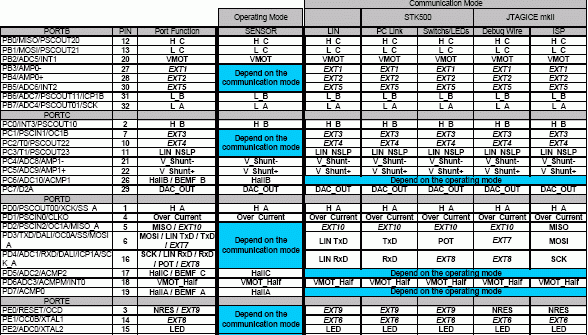
Figure 18. Purpose of the I / O ports of the microcontroller and communication modes
Operating mode
Two different modes of operation are supported. Set jumpers JP1, JP2 and JP3 in accordance with Figure 19 to select one of these modes. In these application guidelines, only mode using sensors is used. Full description The hardware is given in the user manual for the ATAVRMC100 set.

Figure 19. Select control mode using sensors
Figure 19 shows the source settings of the jumpers that comply with the use of software associated with these application guidelines.
The program that comes with the ATAVRMC100 board supports two modes of operation:
- engine launch by maximum speed without external components.
- adjusting the engine speed using one external potentiometer.
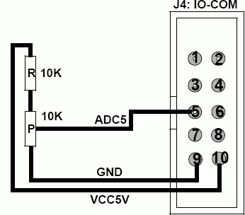
Figure 20. Potentiometer connection
Conclusion
In these recommendations for use, a hardware and software solution for controlling the control unit of the DC is presented using sensors. In addition to this document, the full source code is available for download.
The program library includes starting and controlling the speed of any BCEPT with built-in sensors.
The schematic diagram contains a minimum of external components necessary for control of BKEPT with built-in sensors.
The capabilities of the CPU and the memory of the AT90PWM3 microcontroller will allow the developer to expand the functional solution.

Figure 21. Concept electrical circuit (part 1)
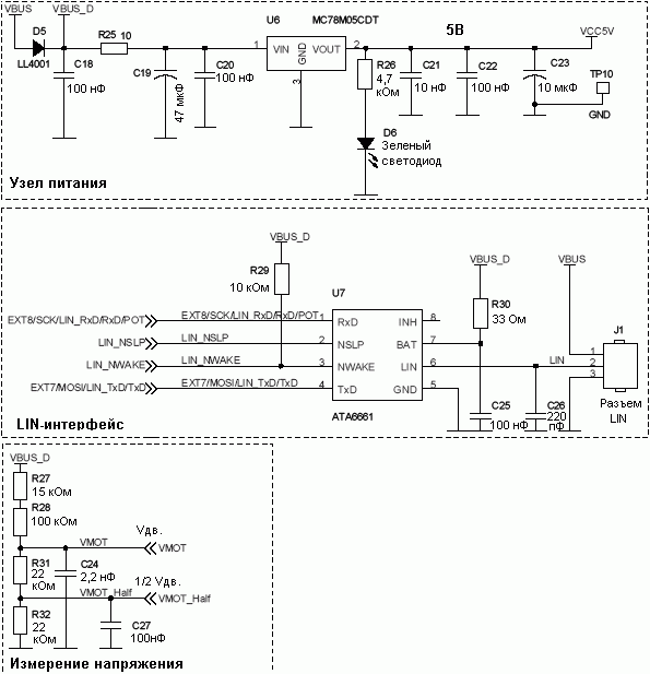
Figure 22. Concept electrical diagram (part 2)

Figure 23. Concept electrical circuit (part 3)
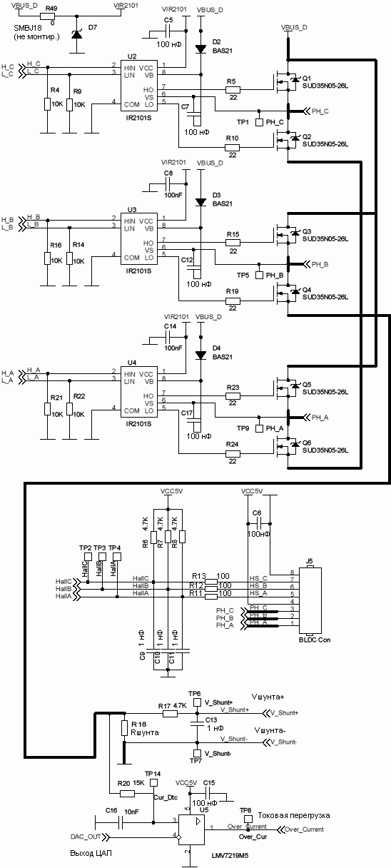
Figure 24. Concept electrical diagram (part 4)
Documentation:
Fantastic renovation of apartments and repair cottages for big money.

