Steering gear - A combination of mechanisms, aggregates and nodes providing ship management. The main structural elements of any steering device are:
- the working body - the pen steering wheel (steering wheel) or the rotary guide nozzle;
- Baller, connecting the worker with a steering wheel;
- steering drive, transmitting effort from the steering machine to the worker;
- steering machine that creates an effort for turning the worker;
- Control drive that connects the steering machine with the post of control.
At the modern ships, the hollow streams, consisting of horizontal ribs and vertical diaphragms coated with steel trim (Fig. 4). The trim is fixed to the frame with electric plates. Inner space The steering wheel is filled with resinous substances or direct polyurethane foam PP3s.
The steers are depending on the location of the axis of rotation:
1) balancing (Fig. 4, 6), the axis of rotation passes through the pen steering;
2) nonbalance (Fig. 5), the axis of rotation coincides with the front edge of the pen;
3) Semi-abandoned rudders.
The moment of resistance to the rotation of the balancing or semi-abandoned steering wheel is less than nonbalansive, and, accordingly, less required power of the steering machine.
By the method of fastening, the steers are divided into:
1) suspended, which are attached to the horizontal flange compound to the baller and are installed only on small and small small mining courts.
2) Simple.
A simple single-rope wheel steering wheel (see Fig. 4) The pin rests on the stubborn glass of the heel of Ahterstevnya. To reduce friction, the cylindrical part of the pin has a bronze cladding, and the bronze bushing is inserted into the heel of the acht. A steering wheel with a ballee is a horizontal flange on six bolts or conical. When cone connection, the conical end portion of the baller is inserted into the conical hole of the upper ends of the steering wheel and is tightly tightened with a nut, access to which is provided through the cover set on the screws included in the rudder. The curved baller makes it possible to separately dismantle the steering and baller (with their mutual reversal).
A simple dock-resistant nonbalance steering wheel (Fig. 5) is closed with a leaf diaphragm and a cast head having a flange for connecting the steering wheel with a ballers and a loop under the upper pins. Bowls, bronze or other bushings are inserted into the ruder support loop.
Insufficient rigidity of the lower support of the balancing steering wheel often causes the vibration of the vessel's feed and the steering wheel. This disadvantage is absent from the balancing steering wheel with a removable ruderpost (Fig. 6). In the pen of such a steering wheel, a pipe is mounted through which a removable rule is passed. The lower end of the ruderpost is fixed by the cone in the heel of the Ahterstevnya, and the top fasten the flange to the ahtershevny. Bearings are installed inside the pipe. Ruderpost in places of passage through bearings has a bronze lining. Fastening the steering wheel to the baller - flange.
Auxiliary rowing screw is placed in the active steering wheel (Fig. 7). When the steering wheel, the direction of the auxiliary screw is changed and an additional moment that turns the vessel occurs.
The direction of rotation of the auxiliary screw is opposite to the direction of rotation of the main one. The electric motor is placed in the steering wheel or in the tiered compartment. In the latter case, the electric motor is directly connected to the vertical shaft transmitting rotation to the gearbox gearbox. The screw of the active steering wheel can provide a ship speed up to 5 tons.
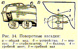
In many ships of the fishing fleet, instead of the steering wheel, the rotary guide nozzle is installed (Fig. 8), which creates the same steering force, lateral force with smaller corners of the smoker. Moreover, the moment on the ball-leverage of the nozzle is approximately two times less than the point on the balller of the steering wheel. To ensure the sustainable position of the nozzle at shorts and increasing its steering to the tail part of the nozzle in the plane of the baller's axis, the stabilizer is fixed. The design and fastening of the nozzle is similar to the design and fastening the balance sheet.
Fig.4 Workers of steering devices: The steering wheel is a balance sheet.
1 - Baller; 2 - flange; 3 - trim feather steering; 4 - delold the fairing; 5 - vertical diaphragm; 6 - horizontal edge; 7 - heel Ahterstevnya; 8 - nut; 9 - washer; 10 - steering pin; 11 - bronze pine facing; 12 - Bronze bushing (bearing); 13 - stubborn glass; 14 - Channel to dismantle a stubborn cup. 
Fig.5. Workers of the steering devices: the steering wheel of the dual-resistant nonbalance.
1 - Baller; 2 - flange; 3 - trim feather steering; 7 - heel Ahterstevnya; 8 - nut; 9 - washer; 10 - steering pin; 11 - bronze pine facing; 12 - Bronze bushing (bearing); 15 - Helmport pipe; 17 - Ruderpost; 18 - Bakat. 
Fig.6 The steering wheel is balancing with a removable rulepost.
1 - Baller; 3 - trim feather steering; 7 - heel Ahterstevnya; 11 - bronze pine facing; 12 - Bronze bushing (bearing); 15 - Helmport pipe; 19 - a ruderpost flange; 20 - removable ruderpost; 21 - vertical pipe. 
Fig. 7 Active steering wheel.
3 - trim feather steering; 4 - delold the fairing; 23 - gearbox with a fairing; 24 - stabilizer;
Baller is a curved or straight steel cylindrical bar, derived through the Helmport pipe into the tape branch. The connection of the gelmport pipe with the outer sheaving and the deck flooring is waterproof. In the upper part of the pipe, the sealing gland and bearing of the baller, which can be supported and stubborn.
The steering must have drives: the main and auxiliary, and when they are located below the cargo waterline, an additional emergency, located above the deck of bulkheads. Instead of auxiliary drive, it is allowed to install a dual main, consisting of two autonomous aggregates. All actuators must act independently of each other, but, as an exception, they are allowed to have some general details. The main drive should work on energy sources, auxiliary can be manual.
The steering drive design depends on the type of steering machine. Electric and electro-hydraulic steering machines are installed on ships of the fishing fleet. The first is performed in the form of an electric motor direct current, second - in the form of a set of electric motor - a pump in combination with plunger, blade or screw hydraulic drive. Manual steering machines in combination with stormed, rolly or hydraulic steering wheel drive are found only on small and small mining courts.
The remote control of the steering machine from the steering wheelhouse provide teledamic transmissions, called the steering telecasts or steering teleclosures. In modern fishing vessels, hydraulic and electric steering television shows were used. Often they are duplicated or combined into electro-hydraulic.
The electrical TV shows consists of a special controller located in the steering tube and the associated electrical system With a steering device of the steering machine. Controller control is carried out using the helmet, handles or buttons.
The hydraulic television shows consists of a manual pump driven by steering wheel, and tubes that bind the pump with a steering device of the steering machine. The working fluid of the system is the non-freezing mixture of water with glycerol or mineral oil.
The management of the main and auxiliary steering drives is independently produced from the undercarriage, as well as from the manual separation. Transition time from the main on auxiliary drive should not exceed 2 min. If there are posts of control of the main steering wheel drive in the steering and commercial logging, the failure of the management system from one post should not impede control from another post.
The wheelchair angle is determined by the axiimeter installed in each post. In addition, on the steering sector or other parts, rigidly connected with the baller, is applied to the scale to determine the actual position of the steering wheel. The automatic consistency between speed, the direction of rotation and the position of the helm and the speed, the side and the angle of the steering wheel is provided by the servo.
The brake (stopper) of the steering wheel is designed to hold the steering wheel during emergency repair or during the transition from one drive to another. The most commonly used ribbon stopper, clamping directly baller steering. Sectoral drives have shoe stops in which brake shoe pressed against a special arc on the sector. In hydraulic drives, the role of the stopper is performed by valves, overlapping access working fluid to drives.
Holding the vessel at a given course with favorable weather conditions without the participation of the steering provides the steering wheel, the principle of operation of which is based on the use of a gyrocompas or magnetic compass. Conventional management bodies are related to autorone. When the vessel falls on the specified course, the steering wheel is installed in the zero position and include the auto-power. If under the action of wind, unrest or flow, the vessel deviates from the specified course, the system motor, having received a pulse from the compass sensor, ensures the return of the vessel to the specified course. When changing the course or maneuvering, the steering wheel is disconnected and passed to normal steering.
General registry requirements for steering device are as follows:
- Each vessel, with the exception of ship barges, must have a reliable device that provides its turnover and stability on the course: steering device, a device with a swivel nozzle and others;
- taking into account the appointment and special operation of the vessel, the use of these devices together with the means active control vessel (saouse).
- the intelligence time of the fully immersed steering wheel or the rotary nozzle is the main drive (with the highest speed of the front turn) from 35 ° of one side by 30 ° of the other should not exceed 28 s, auxiliary (at a speed equal to half the highest speed of the forefront or 7 nodes, depending From what value is more) from 15 ° of one side by 15 ° of another - 60 s, emergency (at no less than 4 nodes) is not limited.
In the Register of Part III of Chapter 2, the requirements for all elements of the steering device are presented, formulas are given to calculate the effectiveness and steering and turning nozzles.
The rotation of the vessel is performed using a steering wheel, which is installed in the stern of the vessel. When deviating or, as it is customary to speak, when the steering wheel, the power of water pressure will be operated onto a steering wheel on the steering wheel. This force creates a torque rotating the vessel towards that board, on which the steering wheel was turned. To shift the steering wheel, some moment is applied to it, the value of which, and consequently, the power of the steering machine depends on the power of water pressure on the steering wheel and the point of the application point of the equal pressure forces from the rotation axis.
Depending on the location of the axis of rotation, the rudders are divided into two types (Fig. 73): non-balance and balancing. The axis of rotation of the nonbalansive steering wheel passes along the front edge of the steering wheel, and the balance sheet - through the pen steering wheel. At the Balancing Steering Point of Pressure Forces application is closer to the axis of rotation, so it is necessary for its smoker, less power is needed, which is a significant advantage.
The feather of the steering wheel on the vessels of the old building was performed from a thick steel sheet, supported by forged ribs. Such flat rudders at the movement of the vessel created significant resistance and are now rarely applied (on powerful icebreakers).
Fig. 73. Types of steering wheel: A - nonbalance; B - balancing
Modern vessels mainly have hollow (streamlined) rudders (Fig. 74), whose feather consists of a frame, on two sides, a sheet-sheet\u003e - steel. This design reduces water resistance to the vessel. For an even greater decrease in the resistance of the flow of water to Peru steering wheel at the rowing shaft level, the fairing in the form of a pear-shaped endowders is added.
The frame of the hollow steering wheel consists of horizontal edges and vertical diaphragms. From above and below the pen is closed with end sheets. The internal space for ensuring waterproof and corrosion protection is filled with resinous substance or direct polyurethane foam.
At the top of the pen steering wheel on the flanges or with the help of the cone is connected to the baller. With the flange connection at the lower end of the baller and in the upper part of the steering wheel there are horizontal flanges bonded by bolts. Sometimes baller at the bottom of the conical and inserted into the same hole to the top of the steering wheel. Since the flange is usually somewhat shifted relative to the axis of rotation, the shoulder is formed, facilitating the steering wheel.
The upper end of the baller is removed on one of the decks, on which the steering wheel is located. So that the water does not penetrate into the vessel's housing through a cutout for skipping a baller, the latter is placed in a helmport pipe, the combination of which with an outer skin and a deck flooring waterproof. At the top of the pipe, the gland is installed, preventing water from entering the vessel. Above the gland is the bearing, which is the upper support of the power baller. Depending on the method of fastening to the vessel, the vessels are hungry, suspended, semi-linful and with removable rudel.
![]()
Fig. 74. Feather of the hollow steering wheel: 1- baller; 2 flane; 3-end leaf; 4-pear-shaped endowing-fairing; 5-vertical diaphragms; b - horizontal ribs; 7-shelter
![]()
Fig. 75. Handles; A-hinged; b - suspended; in - semi-lining, g - with removable ruderpost; / -helmport pipe; 2- ballerler; 3-flange; 4- steering loop, 5-removable casing; 6- Ruderpost; 7- tienets; 8 feather steering; 9-nut; 10-washer; 11-steering pin; 12- bronze cladding; 13- Bakat; 14- bronze bushing; 15-stubborn glass; 16- resistant reference bearing; 17-gallery pipe; 18- emphasis; 19- bearing; 20- Corps; 21-gland; 22- resistant reference bearing; 23- fairing; 24- cone baller; 25- conquer socket of the steering wheel; 26- Flange Ruderpost; 27-removable ruderpost; 28- vertical trumpet
The mounted steering wheel (Fig. 75, a) is hung on a power with steering pins. The lower part of the pin has a cylindrical shape, and the upper one is a conical with a slight bias. Part of the pin, located above the cone, has threads. The pin with a conical part is introduced into the hole of the steering loop and tighten the nut, which ensures its dense landing. In the loop rudepost, the pins put with a small gap, so they can rotate freely. To reduce friction, the cylindrical part of the pin has a bronze lining, and the loop of the ruder site is a bushing of a bunch or textolite. In the backbone to reduce friction under the pin they put a stubborn glass that perceives the vertical load.
The streamlined mounted steering wheel is usually placed on a rule on two pins, which makes it possible to immediately bring the pen steering to the ruderpost and reduce the vortex formation in the gap between the rudposte and the steering wheel. The rule in this case has a streamlined form, which further reduces water resistance. On the icebreakers, the steering wheel is hung on 3-4 pins, which increases the reliability of the attachment.
The pendant steering pen (Fig. 75, b) has no supports and is supported only by the baller, which relies on the support and resistant bearings installed inside the case.
The feather of the semi-lining steering wheel (Fig. 75, c) has only one pin at the bottom of the steering wheel. At the top of the feather, the steering wheel is supported by the baller. The vertical load in the semi-lining steering wheel can be transmitted both to the pin and on the baller. In the first case, the pin in the splay of D.Ledzheny rely on the stubborn glass, and in the second the baller is supplied with a stubborn bearing.
Recently, the worst with removable rudepost is becoming increasingly widespread (Fig. 75, d). The feather of such a steering wheel has an open
The vertical pipe through which the removable rule passes. The lower end of the rule is fixed by a cone in the groove, and the top flange is fixed to the ahterstevnya. Since the ruderpost in this case is the axis on which the steering wheel rotates, the bearings are installed inside the pipe, and the rule in these places has a bronze cladding.
The steering machine provides steering wheel in accordance with the signal from the bridge and is part of steering.
The steering device consists of four parts:
- control systems,
- force aggregate,
- steering drive,
The power unit and the steering wheel form actually the steering machine.
The control system or telecast transmits a signal from the bridge to turn the steering wheel and ensures the operation of the power unit and the steering drive until the specified power rotation angle is reached. The power unit creates an effort required to rotate the steering wheel to the specified angle. The steering wheel drive is a device by which the steering is moved directly.
The steering must meet the following requirements:
- have two independent steering tools (if there are two power units, auxiliary or reserve power unit is not required);
- the power and torque of the unit should be such that the rollover of the steering wheel with 35 of one side by 30 of the other was carried out at maximum speed the vessel during not exceeding 28 s;
- an auxiliary steering wheel should provide a steering wheel of a steering wheel with 15 single boards by 15 more than 60 s at an outflow speed equal to half of the maximum, but not less than 7 nodes;
- the steering machine must be protected from shock loads;
- the emergency control of the steering machine from the TPLED compartment should be provided;
- Tankers having a gross capacity of more than 10,000 rd, must have two independent steering machine control systems from the bridge.
Steering machines may have a steam, electrical and hydraulic drive.
On modern sea ships, steering machines are used with hydraulic plunger or blade drive.
5.10.2. Electro-hydraulic steering machines
Electro-hydraulic steering machines consist of the following main nodes:
- hydraulic steering drive - device rotating balller steering;
- pumping unit (pump and engine), providing the power of hydraulic steering drives with working fluid;
- organs of the distribution of the working fluid and the pump control system and the distribution of the working fluid;
- power pipelines, safety valves, compensators; Dynamic loads, power limiters and other elements depending on the design of the steering machine.
Hydraulic steering drives are hydrodic engines that provide limited angles of rotation of the executive shaft, which is the ballerger of the steering wheel. Plunger actuators received the most widespread. Depending on the value of the required torque, two or four plunger drive. The schematic diagram of this drive is shown in Fig. 74.
Fig. 74. Circuit diagram of a plunger drive:
1- pump electric motor, 2- pump, 3- safety valve, 4- coupling, 5-tapel, 6-cylinder, 7-tank
Plungers are moving in hydraulic cylinders, turning the rifle of the hinge crossbow in the fork of plungers. The drive is served by two pump variable pumps. Each of the pumps is reported to pipelines with all hydraulic steering cylinders for suction and oil discharge.
Near the cylinders there is an oil tank, which is provided with non-refundable valves to automatically replenish oil leaks from the system. Bypass valve combined with safety valve and opens for oil tool in case strong blows Waves in the feather steering wheel. In this case, the plunger is shifted, which in turn causes a change in the supply of the pump, which pumps oil into the appropriate cylinder, and the steering pen returns to the previous position. To protect against breakdown control levers, a buffer spring is used when shock load. Under normal operating conditions, one of the pumps works. If you need to provide an accelerated steering wheelchair, both pumps can be used simultaneously.
In fig. 75 shows the device of the 4-plunger electro-hydraulic steering machine.
Such a machine creates a larger torque and has increased reliability in case of failure of various parts of the installation. Each pump can work on all cylinders or two cylinders of the right or left side.
The presence of a block of control valves combining safety valves, shut-off pump valves and cylinders, bypass valves, increases the survivability of the steering machine.
For normal conditions One pump can provide all cylinders. In an emergency, two pumps with manual control for the operation of two right side plungers, two - left side, two nasal or two feed plungers can be used.

Fig. 75. 4-plunger electro-hydraulic steering machine:
1, 23,25 - Pump Pumps, 2,9,19,22 - Cylinder shut-off valves, 3,10,18,21 - hydraulic cylinders with plungers, 4,8,17,24 - air and pressure gauge valves, 5 , 7,40,47.48 - Oil pipelines cylinders, 6,16,20 - electric motors, 11.27 - bypass valves, 12.37 - connecting links, 13,26 - floating levers, 14 - buffer springs, 15 - RFwenel, 28 - flywheel of local control post, 29,30,31,32,33,34 - non-returnable suction replenishing valves, 35 - telecom receiver, 36- connecting rod pumps, 38,39,49,50,51,52 - shut-off Pump valves, 41,42.43, 44.45,46,53,54 - Oil pipelines between valves, 55 - oil replenishment tank.
In order for the system to be ready to work, each cylinder of the steering drive must be filled with oil, then set filling plugs and close air cranes. The bypass valves should be open, and the tank for replenishment is filled. Air cranes on the pumps are left open until the flowing oil contains air bubbles. Using the manual control mechanism, the pumps are set to the minimum feed position and rotate them manually, removing the air first from one and then from another pairs of cylinders. After that, the pump electric motor and start checking the steering machine in action. At the same time, air from cylinders and pumps through the appropriate cranes are once again removed.
In electro-hydraulic steering machines with rotary blade drive Fig. 76 The blade rotor is firmly fixed on the ballet.


Fig. 76. Blade electro-hydraulic drive:
a - concept scheme, b - incision, 1 - electric motor, 2 - pumps, 3 - safety valve, 4 - Case, 5 - Baller, 6 - Rotor, 7 - Oil cavity, 8 - Oil tank, 9 - cover
The rotor can be rotated in the housing that is attached to the ships set. The space between the rotor blades and the jumpers of the housing form the cavity, the volume of which changes when the rotor is rotated. The cavities are compacted by a special packing. On both sides of the swivel blades, pipelines are connected, each of which has an annular collector. When the oil is applied to all cavities on the left side of the rotary blades and when sucking the oil from all cavities on the right side, the rotor is rotated clockwise. For turning in the opposite direction, suction and discharge are changed in places.
The drive usually has three blades, thereby ensuring a steering wheel terminal by 70 0.
The enclosures are performed by the playback function that limit the steering wheel.
The steering device is the main means that ensures reliable management of the vessel under any swimming conditions. Its design must meet the requirements of the river register, which makes the vessel of this type. It consists of a steering wheel, steering, steering machine, an axiometer, and sometimes the steering pointer. Currently, turning nozzles, active rudders and podium devices are used on ships.
Depending on the shape and arrangement of the pen with respect to the axis of rotation, are divided into simple, balancing and albalance (Fig. 33).
It is simple called the steering wheel, in which the feather is located on one side of the axis of rotation (baller). In the form of a profile in terms of simple steers can be flat (lamellar) and streamlined. The balancing is called the steering wheel, in which the feather is located on both sides of the baller. The front of the pen in relation to the baller is called the balancing part. Depending on the design of the vest part, the balancing steers may have a lower fastening support or be suspended. The suspension balance of the wheel is mounted on the deck or in the housing of the vessel (ahterpics) on a special foundation.
 The hembalance differs from the balance sheet of the fact that its balancing part is less in height than the entire feather of the steering wheel, and is located only at the bottom.
To ensure controllability in the back of the pushers are equipped with reverse steering (so-called flanking), which are installed ahead of the rowing screws with such a calculation so that the water flow occurs when operating screws on reversewas directed to these steeringles.
Swivel nozzle (Fig. 34) is a metal cylinder, inside of which is a rowing screw of the vessel. With its upper part, the cylinder is attached to the baller, with which it can be rotated relative to the rowing screw.
 The outlet opening of the nozzle, for greater efficiency of its action on the controllability of the vessel, the plate steering wheel, which is often referred to as the stabilizer. In addition, in addition to the stabilizer, nozzles are sometimes equipped with radial ribs and washers.
The submissive device is a pipe installed across the vessel housing through which the intake water is pumped from the board using a centrifugal pump or screw. In the first case, the sweeter is called the pump, and in the second tunnel. The outlet holes in the sides have a profiled endower and grille to protect the pipe (tunnel) from foreign objects. The principle of the device is that when pumping (run) of water from one side to another due to the reaction of the ejected jet is created, the perpendicular diametrical plane of the vessel is created, which contributes to the movement of the vessel to the right or left. With the change in the direction of the jet emission, the direction of movement of the vessel will be changed.
 Steering drives serve to transfer effort from the steering wheel on the balller's power. Secto-type actuators with flexible or rigid transmission were most common.
.jpg) Fig. 37. Scheme of electro-hydraulic steering
Fig. 37. Scheme of electro-hydraulic steering
With a flexible transmission, which was called the sturrosive, force from the steering machine to the sector is transmitted using a chain, a steel flexible cable or a steel rod. The chain is usually put on a plot passing through an asterisk of the steering machine, and on direct sections - steel cable or bar. Castles, clamps and tallpins are used to connect individual sturrosteral sections. To change the direction of the Sturros, on curvilinear sites, sending guide blocks - ROULS, and to protect the strus from abrasion about the deck - deck rollers.
Recently, all large application Hard transfers are roller and gear.
Roller transmission (Fig. 35) is a system of rigid links of rollers interconnected by universal joints or conical gear gear gears.
The gear gear is a system of gears and rollers, while the force of the steering machine is transmitted to the steering steering sector using a worm through the gear.
On ships having two or more steering wheel, the steering wheel has a more complex design.
Steering machines for their design are divided into manual, steam, electrical and hydraulic.
Manual steering machines are easy to design, so they are installed on small vessels (boats) and on a non-intended fleet. The main elements of manual steering machines are the screw wheel and the associated drum on which the circuit or cable is wound (with a storm transmission). If the vessel does not apply not a storm, but a roller transmission of effort from the steering wheel to the steering wheel, the feedstock is connected to a gear or worm-driven, which is mechanically connected to this roller transmission.
Steam steering machines are placed on steamboats as the main.
Most modern boats found the use of electric steering machines. They are installed in the steering wheelhouse or in the tiered branch located in the vessel's feed compartment. The electric motor is activated from the control panel from the steering wheelbitch. The control panel has a manipulator. The relevant contacts are included with the rotation of the handle of the manipulator, and the appropriate contacts are turned on, and the motor shaft begins to rotate into the right or left side, changing the position of the vessel steering. If the steers turn onto a particular board before its extreme position, contacts are blocked and the electric motor is automatically turned off.
.jpg) Fig. 38. Scheme of the hydraulic steering device of the "Meteor" ship:
Fig. 38. Scheme of the hydraulic steering device of the "Meteor" ship:
1-cylinder-performer; 2-hydraulicel; 3-steer; 4-cylinder sensor; 5 steering machine; 6-consumable tank; 7-balloon with air; 8-manual emergency pump; 9-hydraulic pump; 10-hydroaccumulator
On a note: Kievsky navigator conducts teaching driving and improving the driver's skills.
When installing electrical steering machines, the backup (spare) manual steering wheel is mandatory. In order not to perform any switches when switching to manual control Apply Differential Fedoritsky.
This differential (Fig. 36) is arranged and works as follows. Worm gears (wheels) 2 and 5 are freely rotated on the vertical shaft 6. The internal end surfaces of these worm gears are rigidly connected to the conical gears. The vertical shaft with the help of a knocker is enshrined with a casset 4, at the end of which conical satellite gears 3, associated with the conical gear wheels 2 and 5. On the upper end of the shaft 6 shipped on the key of the cylindrical gear 7, incorporating the gear with the toothed sector Steering drive.
The worm screw 9 rotates the electric motor of the steering device. The worm screw 8 is associated with the manual spare drive and when the electric motor is fixed. As a result, it turns out the stipulated worm gear 5 with the bottom of the conical gearbox attached to it. The worm gear 2 rotates the screw 9, and its conic top gear makes the satellite gears rotate 3. But since the gear 5 is stroke, the gears 3 are rolled along its conical part, turning the crossbar 4, associated with her shaft 6 and gear 7. gear sector, The connected gear 7 turns.
When manually controlled, the worm gear is turned out to be a worm gear 2. Then, when the worm screw is rotated, 9 gear satellites are circulating a conical gear wheel 2, due to which the shaft rotates 6.
Fedoritsky's differential is both a regulator that reduces the number of turns of the shaft 6 compared with the turnover of the electric motor shaft (i.e. the worm screw 9). The regulator is enclosed in the case 1.
Hydraulic steering machines, despite a number of positive qualities, obtained less distribution on a river fleet. They are installed mainly on large and high-speed vessels with underwater wings. The principle of their work is as follows (Fig. 37): The electric motor 1 drives the pump 2, pumping the oil into the right 5 or left 3 hydraulic cylinder, as a result of which the piston 6 moves in the cylinders and the rumor 4 connected to it. Handles of the ship.
The hydraulic steering wheel drive of the ship on the submarine wings "Meteor" is presented in Fig. 38. It consists of a power system and a system of controlling the hydraulic agent.
In the power (open) system, the system includes hydraulic pump with an electric drive, a hydraulicer, hydroaccumulators, a consumable tank, filters, an air balloon with a capacity of 8 l with a pressure of 150 kgf / cm2, a manual emergency pump, fittings and pipelines.
The system of control system (closed) consists of cylinders-sensors, activated from the steering wheel steering wheel, cylinders, filling tank, reinforcement and pipelines.
As a working fluid, AMG-10 Aviation mixture is used in the system (aviation oil for hydraulics).
In the steering wheel, the combination of manual and hydraulic control is provided, which makes it possible in the event of a hydraulic control failure immediately go to manual.
All major vessels regardless of whether they have steam, electrical or hydraulic machinesmust have spare manual control. The transition time from the main steering steering should not exceed 1 min.
The effort on the handle handle handle does not exceed 12 kgf.
The duration of the steering wheel from the side of the board on self-propelled vessels with mechanical or electrical machines should not exceed 30 s, and with manual - 1 min. An axiometer is a mechanical or electrical device that serves to indicate an angle of rejecting the steering wheel. In the new courts, an axiometer is installed on the control panel.
Steering pointers are constructively connected only with the head of the power baller, they show the true position of the steering wheel, regardless of the operation of the steering drives. The reading of the electrical steering pointer can be removed directly into the steering wheelhouse of the vessel.
The steering device includes a steering machine with a manual, sector, screw or hydraulic drive and actually steering wheel, main and manual (spare) steering wheel.
The basic requirements for steering devices include:
The maximum wheelchair angle for maritime courts should be 35 degrees, and for the vessels of the river fleet can reach 45 degrees;
The duration of the wheelchair from one side to another side should be no more than 28 s;
Steering machines must ensure reliable operation of the steering device in the conditions of a ship pad with a roll of up to 45 degrees, a long roll - up to 22.5 degrees and a differential - up to 10 degrees.
Defectoscopy and repair. The characteristic defects of the steering device include:
Wear of the shek of the roaring baller, its bending and twisting;
Wear bearings, pins, lentils;
Damage to the connection of the baller with the pen steering;
Corrosion and erosion destruction, crack steering;
Power centering disorders.
Technical condition The steering device is determined before each regular examination of the vessel (afloat or in the dock), before and after the repair of the vessel and, if the appearance of a malfunction.
The flaw detection of the steering device is carried out in two stages.
At the first stage, without any dismantling work, the overall technical condition of the steering device is determined by the external inspection method (from the boat and a diving inspection): the correspondence of the position of the steering wheel and pointers (to determine the values \u200b\u200bof the steering baller); Clamps in bearings and height from the heel of Ahterstevnya to the steering wheel (HR):

In the second stage, the steering device is dismantled and disassembled.
Dismantling, disassembly. Before dismantling the steering wheel in the stern unit, the flooring is installed, the hoists hang, the slings, jacks and the necessary tool are preparing. Disassembly includes the following operations:
Disassemble manual steering wheel, brake device and remove from engagement toothed gear mechanical drive;
Remove from the head of the tape of the steering wheel the toothed sector, a tapel;
Ballarler bearings are disassembled, separated and disassemble the baller with RUDERPIS;
Raise and remove the feather of the steering wheel from the feed podzer and lowered the dock on the deck, the vessel or on the pier;
Lower the filling baller through the Helmport pipe on the deck;
They knock out lentils from the ahterstevny heel socket through a hole having in it.
The bearing sleeve pressed in the heel of Ahterstevnya, in the case of a large wear, cut down the length and after the crumpled, its edges are knocked out of the nest.
When disassembling the steering device, the greatest difficulty represents the dismantling of the tape from the steering baller. As a rule, the tiller is pressed on the head part of the baller in the hot condition with tension. Sometimes the head of the removal head is cut by a gas cutter during disassembly and conduct a detailed flaw detection with the subsequent repair of the steering parts.
The wear of the shek of the baller is eliminated by a gate (the allowable decrease in the diameter of the cervical cervix is \u200b\u200bnot more than 10% of the nominal value), or the electron powder followed by mechanical processing.
The curved baller rules in the hot condition with heating to a temperature of 850-900 s, and after editing it is subjected to annealing and normalization. The accuracy of editing is considered satisfactory if the baller's beating in the bend place will be in the range of 0.5-1 mm. After editing and normalization, the plane of the flange of the baller and the necks are fluttered on the lathe.
When twisting the baller to 15 degrees, the old key groove is brewed, perform heat treatment of this area to remove twisting voltages, mark and milling a new key groove in the plane of the steering wheel.
When wearing the bearing sleeve and lentils, they are replaced. Lentil is made of steel with a subsequent handling.
The flange connection defect with a pen with a pen is eliminated by turning, with a shining groove and installing a new key.
The most frequent damage to the steering wheel belongs are dents and ruptures of the sheets of the steering wheel. With the overall wear of the trim of the steering wheel (more than 25% thickness), the sheets are replaced.
Cracks and corrosion destruction of welds are eliminated with cutting and welding. Before replacing the trim, the wheel of the steering wheel is removed from its inner cavity (the product of the stone coal distillation), which is a solid glass-like mass of black. After repairing in the inner cavity of the pen steering wheel, warpets in the hot condition (when heated warpets becomes liquid).
Before setting a simple steering wheel in place check the centering of the holes of the ahterstevny loop by the stretched string method. Over the base of the center of the hinges of the Achterstevnya take the axis of the gelmport bearing and the bearing of the heel of the Ahterstevnya.
The quality of repair and installation of the steering device is estimated according to the results of the centering, the magnitude of the installation gaps in the bearings, the correspondence of the position of the steering wheel and pointers.
Total criterion technical status The steering is the time of the steering wheel during the vessel's running tests, which should not exceed 28 s. Tests of the steering device should pass with the excitement of the sea no more than 3 points, on the complete front of the vessel at the rated frequency of rotation of the rowing shaft.
Technique control of the steering device for technical condition.
The technique provides for the definition of the overall technical condition of the steering device based on its external examinations without any dismantling work (inspection from the boat, diving inspection) and the control of the following parameters:
Level of vibrating the steering baller; .
Steering time of the steering wheel from the side of the board;
Fluid pressure in hydraulic cylinders for electro-hydraulic steering machines;
The forces of the operating current of the executive motor for electrical steering machines;
The presence of metal and abrasive wear products in the working fluid.
In terms of the level of vibrating the rook baller, the state of the gaps in the steering bearing is controlled.
The frequency control of the steering parameters is shown in the table:

Achieving the maximum permissible value of at least one of the parameters indicates the need for maintenance (repair) steering.
Based on controlling the actual technical state of the steering, the following works can be performed: replacement or replenishment of lubricant in bearings, replacing bearings, plunger pairs; In addition, the issue of the need to set the ship to the dock to dismantle the baller is solved due to increased gaps in its bearings and damage to the steering wheel.


