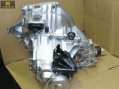
Gasoline motor on the "eight"
The appearance of the VAZ 21083 gasoline engine is directly related to the low quality of domestic rubber products. The fact is that at the very beginning of the release on the machine of Lada Samara, the VAZ 2108 motor was installed, the first domestic power unit developed specifically for cross-placement under the hood of the front-wheel drive car was established.
However, the engine VAZ 2108 had an unpleasant feature inherent in foreign motors with belt drive timing. When the timing belt breaks, the motors' pistons were found with the cylinder head valves, and the latter were bent, which led to an expensive repair of the engine VAZ 2108. On foreign cars, such a breakdown happened extremely rarely due to the high reliability of the timing belt. However, on the first Samara, the discrete of a poor-quality belt was such a frequent phenomenon, which had to urgently improve the engine with the help of specialists of German autoconcers. As a result, a new engine appeared, which became the progenitor of a whole family of power units. Motor assembly VAZ 21083 is not a challenge, it can be performed without the help of specialists.
Setting the crankshaft on the VAZ

Repair of crankshaft
The boar of the VAZ 21083 engine usually consists of disassembly of the unit, the defects of the parts, the crankshaft and cylinders and the assembly of the motor. Disassembling the engine - the case is simple, defecting and boring - also simple procedures. But to collect the motor must be extremely neat, carefully adhering to the instructions.
Let's start, perhaps, with the installation of the crankshaft in the cylinder block. Remember: The numbers of cylinders and the indigenous bearings are considered to be right away along the movement of the car. That is, 1 cylinder is located near the pump and the timing of timing, and 4 - near the clutch and gearbox.
- I turn over the block upside down.
- We put the liners of the native bearings by fixing protrusions in the packages of bed. In 3 bed (middle) put the liner without a groove, and in the remaining 4 - with grooves.
- Majm liners with engine oil.
- Lubricate crankshafts with oil and put it in bed, flywheel flange to 4 cylinder.
- We insert a stubborn semiring in the groove of the middle root bearing. On one side, 2 notches are applied on one side. With these sides and install a semiring to the crankshaft cheeks. White half-ring put in front (from a pulley), yellow - rear (from the flywheel side).
- Turn the semiring so that their tips are flush with the ends.
- We put in the lids of the indigenous bearings inserts without grooves, fixing protrusions in the groove, and lubricate them.
- We put the covers of the indigenous bearings on the corresponding beds with the notches towards the fastening of the generator. 1 The lid is indicated by one notch, 2 - two notches and 2 holes, 3 - three, 4 - four, 5 - two.
- We grab covers with bolts.
- Tighten the cap bolts in such a sequence - first bolts 3 covers, then 2 and 4 and at the end of the bolts 1 and 5 of the covers.
- After that, rotate the shaft if it is stuck, we are looking for a reason and eliminate. If it does not start, check the axial clearance of the crankshaft, if it is greater than 0.26 mm, replacing the semiring thicker. If the clearance is normal, proceed to the installation of the glands and the oil pump.
Installation of the glands and oil pump
The engine lubrication system 21083 consists of an oil pump, an oil worker, filter and channels. After disassembling the engine, all channels must be rinsed with solvent and bleed with compressed air. The oil pump should be installed together with the oltels of the crankshaft, and the oil worker is after installation of the SPG and the flywheel.
The order of installation of the glands and the pump.
- With the help of thick copper or brass spacer and hammer, we drive the rear gland to the holder to the end.
- Lithol or other grease glue the gasket on the other side of the holder.
- Lubricate the inside the inner edge of the rear seal and the flange of the crankshaft.
- We put on the gland assembly with the holder on the flange, for this carefully refuel the inner edge of the gland on the flange with the help of a sharp and soft wooden stick.

Replacement of the gland in the oil pump
- After that, slowly move the holder along the flange to the block of cylinders, grab it with the bolts and align so that its edge completely coincides with the edge of the block. Only after that tighten all the bolts finally.
- As well as the rear, score the front crankshaft gland into the hole of the oil pump.
- Lubricate the inner edge of the gland and gear pump oil. For uniform lubrication, scroll the gears with your finger.
- Lithol or any other consistant glue the gasket to the oil pump.
- Turn the lead gear in such a way that the protrusions on it coincide with cuts on the front of the crankshaft.
- We put on the oil pump on the shaft, the sharp soft wooden stick refill the edge of the gland on the neck of the crankshaft.
- As well as the holder, weching the oil pump to the block itself, we grab the bolts, align the edges and tighten the bolts finally.
Install the connecting rod-piston group
The rod-piston group (SPG) must be established assembly. Press the piston finger into the head of the rod without special tools is not recommended. This procedure is better to entrust professionals.
To install the SPGs, a steel mandrel in the form of a ring is needed. The height of the ring is 2-3 cm, the diameter of the opening is slightly larger than the diameter of the cylinder. Mount the pistons in such a way that the arrow on their bottom (parts adjacent to the valve) was turned toward the oil pump. The connecting rod number and piston must match the cylinder number. Before installing, you need to dilute the locks of the oil-chain and compression rings at an angle of 120 degrees.
Installation algorithm.
- I turn over the block.
- Wipe the dry cloth of the cylinder wall and crankshaft crankshaft.
- Thoroughly lubricate the walls of the cylinders, the side surfaces of the pistons and the inner part of the mandrel.
- We put the mandrel on the cylinder and insert the piston across it assembled with the connecting rod. Press the piston into the cylinder with a round wooden stick (hammer knobs).
- We put the liner into the connecting rod cover, lubricate it with oil.
- We put the block on the side and install the connecting rod cover in such a way that the cylinder number on it and on the connecting rod have on one side. We grab the cover with nuts.
- In the same way, we mount the rest of the pistons assembled with connecting rods. After that, we turn the cylinder block upside down and tighten all 8 nuts fixing the connecting rods.
If you do not have a mandrel, it can be cut out of a piece of steel thick-walled pipe yourself.


