High quality NATALY preamplifier
Schematic diagram, description, printed circuit board
This preamplifier is used for tone correction and loudness when adjusting the volume. Can be used to connect headphones.
For a high-quality path, which has in its composition UMZCH with nonlinear and intermodulation distortions of the order of 0.001%, the remaining stages become important, which should allow the full potential to be realized. At present, many options for implementing high parameters are known, including on the OS. The reasons for developing our version of the preamplifier were the following factors:
When assembling a preamplifier on an op-amp, the threshold of its output voltage, and therefore its overload capacity, is entirely determined by the supply voltage of the op-amp, and in the case of power supply from +\-15V, it cannot be higher than this voltage.
The results of subjective examinations of preamplifiers based on op-amps in their pure form (without output repeaters) and with those, for example, based on a parallel amplifier - show the listeners' preference for the op-amp + repeater circuit, with almost identical parameters "in terms of Kr", this is due to the narrowing of the op-amp distortion spectrum when operating on a high-resistance load and operating its output stage without entering the AB mode, which gives switching distortions, it is practically lower than the sensitivity level of the devices (Kg OPA134, for example - 0.00008%), but clearly visible when listening. That is why, and also for a number of other reasons, listeners clearly distinguish a preamplifier with an output stage on transistors.
A well-known circuit solution containing an integrated repeater based on a BUF634 parallel amplifier is quite expensive (the price of a buffer is at least 500 rubles), although the internal buffer circuit can be easily implemented on a discrete one - for a much more sane amount.
Amplifiers in which the op amp operates in a small signal mode show high performance, but lose according to the results of listening. In addition, they are very critical to set up and require at least a square wave generator and a wideband oscilloscope. And all this with clearly worse subjective results.
The lack of output voltage in the PU circuit (op-amp + buffer) can be eliminated by implementing voltage gain in the buffer, and deep local feedback eliminates distortion. A sufficiently high initial quiescent current in the output transistors of the buffer guarantees its operation without distortion typical of push-pull structures in the AV mode. The presence of a total double amplification of the voltage allows you to achieve an increase in overload capacity by 6 dB, and with a three-fold increase, this figure becomes equal to 9 dB. When the buffer is powered by a +\-30V power supply, its output voltage swing is 58 volts peak-to-peak. If the buffer is powered from +\-45V, then the output voltage from peak to peak can be about 87V. Such a margin will be favorably reflected when listening to vinyl discs that have characteristic features in the form of clicks from dust.
The two-stage implementation of the pre-amplifier is due to the fact that the tone block introduces attenuation into the signal up to 10 ... 12 dB. Of course, you can compensate for this by increasing the gain of the second stage, but, as practice shows, it is better to apply as much voltage as possible to the tone block - this increases the signal-to-noise ratio. In addition, discs recorded with a large crest factor (loud peaks and rather low average loudness) are quite common. This is not a lack of mixing, quite the contrary, because sound engineers often abuse the compressor, trying to fit all the levels of sound volume into the range of the CD. But you can not pretend that such records do not exist. The listener at the same time increases the volume. Thus, the second cascade must have no less overload capacity, in addition, it must have low intrinsic noise, high input impedance and the ability to transmit the real signal without distortion after the timbre block, in which the extreme frequencies of the audio range go with the greatest rise. An additional requirement is a linear frequency response when the timbre block is turned off, a flat PH when testing with a meander, and subjective invisibility of the PU in the path.
The well-proven Matyushkin timbre block is used as a timbre block. It has 4-stage bass control and smooth treble control, and its frequency response is well suited to auditory perception, in any case, the classic bridge TB (which can also be used) is rated lower by listeners. The relay allows, if necessary, to turn off any frequency correction in the path, the output signal level is adjusted by a tuning resistor according to gain equality at a frequency of 1000 Hz in the TB mode and when bypassed.
The balance regulator is built into the OOS of the second stage and has no special features.
The low bias voltage of the OPA134 (in the author’s practice at the output of the second stage is not more than 1 mV) makes it possible to exclude transient capacitors in the path, leaving only one - at the input of the PU, because the level of constant voltage at the output of the signal source is unknown. And, although at the output of the second stage, the diagram shows capacitors of 4.7 μF + 2200 pF - at a zero bias level of about a millivolt or less - they can be safely excluded by shorting. This will put an end to the debate about the effect of capacitors in the path on the sound - the most radical method.
Design characteristics:
Kg in the frequency range from 20 Hz to 20 kHz - less than 0.001% (typical value is about 0.0005%)
Rated input voltage, V 0.775
Overload capacity in the timbre block bypass mode is at least 20 dB.
The minimum load resistance at which the operation of the output stage in mode A is guaranteed is at the maximum range of the output voltage "from peak to peak" 58V 1.5 kOhm.
When using a pre-amplifier only with CD players, it is permissible to reduce the buffer supply voltage to +\-15V, because the output voltage range of such signal sources is obviously limited from above, this will not affect the parameters.
Establishing a pre-amplifier should begin with checking the DC modes of the output transistors of the buffers. According to the voltage drop in the circuits of their emitters, the quiescent current is set - for the first stage about 20 mA, for the second - 20..25 mA. When using small heat sinks, which at +\-30V become mandatory - you can, focusing on the temperature situation, increase the quiescent current a little more.
Selection of the quiescent current is best done with resistors in the emitters of the first two buffer transistors. With a small current, increase the resistance, with a large one, reduce it. You need to change both resistors equally.
With the quiescent current set, then we set the TB regulators to the position corresponding to the most flat frequency response, and, having applied a 1000 Hz signal with a nominal voltage of 0.775V to the input, we measure the voltage at the output of the second buffer. Then we turn on the bypass mode and with a tuning resistor we achieve the same amplitude as with TB.
At the final stage, we connect the stereo balance controller, check for the absence of various forms of instability (the author did not encounter such a problem) and conduct an audition. The setting of Matyushkin's TB is well covered in the author's article and is not considered here.
To power the preamplifier, a stabilized power supply is recommended, with independent windings for PU and relay switching. The technical requirements for nutrition are nothing new. The main thing is the low level of midrange and high-frequency noise, with the suppression of the supply of which the situation in the op-amp is known. About the level of ripples - it should not exceed 0.5 - 1mV.
A complete set of boards consists of two PU channels, RT Matyushkin (one board for both channels) and a power supply. Printed circuit boards designed by Vladimir Lepekhin.
Double Sided Preamplifier PCB:

INCREASE
PCB for TB Matyushkin with relay switching:

ENLARGE The circuit is stable. There is no noticeable voltage ripple at the output, the measurements were carried out on an oscilloscope in the mode of 0.01 div / volt (for mine this is the minimum limit).

INCREASE
Measurement results:
On OPA134 (only the first link of two), the power supply is single-stage, +\-15V:
Knee(1kHz) ............................... -98dB (about 0.0003%)
Kim(50Hz+7kHz)............Less than -98dB (about 0.0003%)
On ORA132 (both links), full version, two-stage power supply:
Knee (1kHz) ............................... -100dB (about 0.00025%)
Kim (19kHz+20kHz) .................... -96dB (about 0.0003%)
In the case of self-excitation of cascades at the RF, mica correction capacitors with a capacity of 100 to 470pF should be soldered in parallel with resistors R28, R88 and complementary to them in another channel. This was found when using transistors BC546 \ BC556 + 2SA1837 \ 2SC4793.
In attachments, you can download all files of circuits and printed circuit boards in SPlan 6.0 and SL 5.0 formats, respectively,
Don't dream, act!
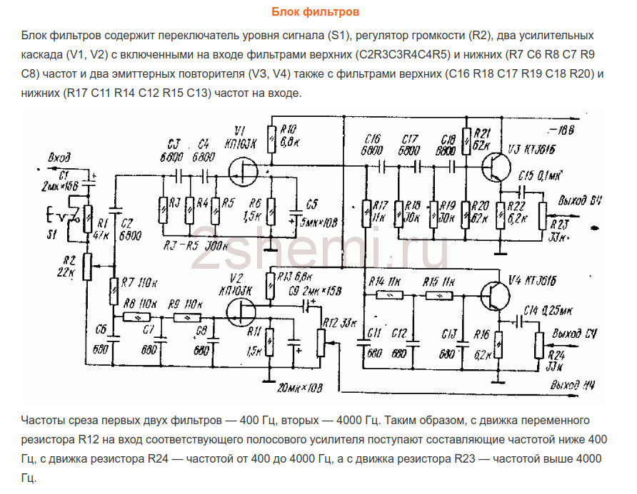
Experiments with various preamplifiers, volume and tone controls have shown that the best sound quality is provided with a minimum number of amplifying stages, with passive controls. In this case, adjustments at the input of the power amplifier are undesirable, since they lead to an increase in the level of non-linear distortions of the complex. This effect was recently discovered by the well-known developer of audio equipment Douglas Self.
Thus, the following structure of this part of the sound amplifying path emerges:
- passive bridge regulator of low and high frequencies,
- passive volume control
- preamplifier with a linear frequency response (AFC) and minimal distortion in the operating frequency range.
The obvious disadvantage of adjustments at the input of the preamplifier is that the deterioration of the signal-to-noise ratio is largely offset by the high signal level of modern sound reproduction devices.
Proposed preamplifier can be used in high quality stereo audio amplifiers. The tone control allows you to adjust the amplitude-frequency response (AFC) simultaneously on two channels in two frequency areas: lower and upper. As a result, the features of the room and acoustic systems, as well as the personal preferences of the listener, are taken into account.
And again a little history
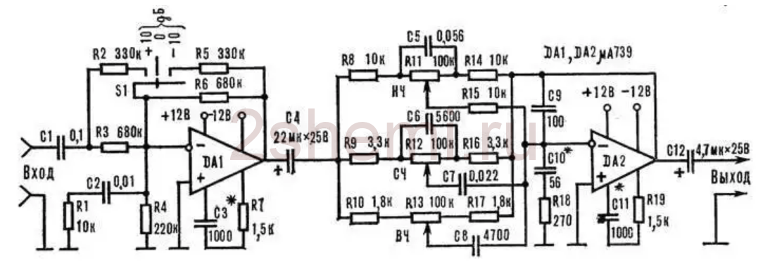
The first contender for the role of a preamplifier with a tone control was D. Starodub's circuit (Fig. 1). But the design never "took root" in the power amplifier: careful shielding and a power supply with an extremely low ripple level (about 50 μV) were required. However, the main reason was the lack of sliding variable resistors.
Rice. 1. Diagram of a high-quality tone control block
Through trial and error, I came up with a simple preamplifier circuit (Fig. 2), with which, however, the sound reproduction system far exceeded the sound of mass-produced equipment, at least, that my friends and acquaintances had.

Rice. 2. Schematic diagram of one channel of the preamplifier for UMZCH S. Batya and V. Sereda
The pre-amplifier circuit of a stereophonic electrophone by Yu. Krasov and V. Cherkunov, which was demonstrated at the 26th All-Union Exhibition of Radio Amateurs-Designers, was taken as a basis. This is the left side of the circuit, including the tone controls.
The appearance of a cascade on transistors of different conductivity in the preamplifier (VT3, VT4) is associated with a discussion of amplifiers with the teacher of the laboratory of television technology at the Department of Radio Systems A. S. Mirzoyants, with whom I worked as a student. In the course of the work, linear cascades were needed to amplify the television signal, and Alexander Sergeevich reported that, according to his experience, top-down structures, as he put it, have the best characteristics, that is, amplifiers based on transistors of the opposite structure with direct connection. In the process of experimenting with UMZCH, I found out that this applies not only to television equipment, but also to sound amplification. Subsequently, I often used similar circuits in my designs, including a pair of field-effect transistor - bipolar transistor.
An attempt to use transistors of different structures in the first stage (composite emitter follower VT1, VT2) did not bring success, because with all the remarkable characteristics (low noise, low distortion), the circuit had a significant drawback - lower overload capacity compared to the emitter follower.
Pre-Amplifier Specifications:
Input resistance, kOhm = 300
Sensitivity, mV= 250
Depth of tone control, dB:
at a frequency of 40 Hz=± 15
at a frequency of 15 kHz=± 15
Depth of stereo balance adjustments, dB=± 6
Since new ideas arose during the design of amplifiers, I gave old designs to someone, or sold them at a fixed rate of watts of output power / ruble. On one of my trips to Leningrad, I took this amplifier with me to sell it to a friend of mine. Volodya said that this guy had a bunch of all kinds of Western equipment, and took the device to him for listening. In the evening he told me the results: the young man turned on the amplifier, listened to a couple of things and was so satisfied with the sound that he gave the money without a word.
To be honest, when I found out that the comparison would be made with imported equipment, I did not particularly hope that the amplifier would impress. In addition, it was not fully completed - there were no top and side covers.
Consider the schematic diagram of one channel of the preamplifier (Fig. 2). High-impedance volume (R2.1) and balance (R1.1) controls are installed at the input. From the middle output of the resistor R2.1 through the transition capacitor C2, the audio signal is fed to the composite emitter follower VT1, VT2, which is necessary for the normal operation of the passive tone control, made according to the bridge circuit. In order to eliminate the attenuation introduced by the tone block and amplify the signal to the required level, a two-stage amplifier based on transistors VT3, VT4 is installed.
The power supply of the pre-amplifier is unstabilized, from the positive arm of the power amplifier. The supply voltage is supplied to the stages VT3, VT4 through the filter R17, C10, C13, and to the input emitter follower - R8, C4. An important role is played by the VD1 diode: without it, it was not possible to completely eliminate the background of an alternating current with a frequency of 100 Hz at the output of the power amplifier.
Structurally, the pre-amplifier is made in a "line", all parts are installed on a printed circuit board, closed on top with a U-shaped screen made of steel 0.8 mm thick.
--
Thank you for your attention!
The calculation was made according to the following relations: R1 = R3; R2 = 0.1R1; R4 = 0.01R1; R5 = 0.06R1; C1[nF] = 105/R3[Ohm]; C2=15C1; C3=22C1; C4 = 220C1.
With R1=R3=100 kOhm, the tone block will introduce attenuation of about 20 dB at a frequency of 1 kHz. You can take variable resistors R1 and R3 of a different value, let, for definiteness, there were resistors with a resistance of 68 kOhm. It is easy to recalculate the values of fixed resistors and capacitors of the bridge tone control without referring to the program or table. 1: we reduce the resistance values of the resistors by 68/100=0.68 times and increase the capacitances of the capacitors by 1/0.68=1.47 times. We get R1 \u003d 6.8 kOhm; R3=680 Ohm; R4=3.9 kOhm; C2=0.033uF; C3=0.33uF; C4=1500 pF; C5 \u003d 0.022 uF.
For smooth tone control, variable resistors with an inverse logarithmic dependence (curve B) are required.
The program allows you to visually view the work of the designed tone control. Tone Stack Calculator 1.3(Fig. 9).

Rice. 9. Simulation of tone controls for the circuit shown in fig. 8
Program Tone Stack Calculator is designed to analyze seven typical schemes of passive tone controls and allows you to immediately show the frequency response when changing the position of the virtual controls.
Rice. 11. Schematic diagram of the tone block and preamplifier for the "student" UMZCH
An experimental test of several instances of operational amplifiers showed that even without a capacitor in the grounded branch of the negative feedback divider, the constant voltage at the output is a few millivolts. However, for reasons of versatility of application, isolation capacitors (C1, C6) are included at the input of the tone block and the output of the preamplifier.
Depending on the required sensitivity of the amplifier, the resistance value of the resistor R10 is selected from Table. 2. One should strive not for the exact value of the resistances of the resistors, but for their pairwise equality in the channels of the amplifier.
table 2 
▼ 🕗 25/02/12 ⚖️ 11.53 Kb ⇣ 149 Hello reader! My name is Igor, I'm 45, I'm a Siberian and an avid amateur electronics engineer. I came up with, created and maintain this wonderful site since 2006.
For more than 10 years, our magazine exists only at my expense.
Good! The freebie is over. If you want files and useful articles - help me!
--
Thank you for your attention!
Igor Kotov, editor-in-chief of Datagor magazine
The main disadvantage of a passive tone control is the low gain. Another drawback is that in order to obtain a linear dependence of the volume level on the angle of rotation, it is necessary to use variable resistors with a logarithmic control characteristic (curve "B").
The advantage of passive tone controls is less distortion than active ones (for example, Baksandal's tone control, Fig. 12).

Rice. 12. Active tone control P. Baksandala
As can be seen from the diagram shown in Fig. 12, the active tone control contains passive elements (resistors R1 - R7, capacitors C1 - C4) included in the 100% parallel negative voltage feedback of the operational amplifier DA1. The transmission coefficient of this regulator in the middle position of the R2 and R6 tone control sliders is equal to one, and variable resistors with a linear regulation characteristic are used for adjustment (curve "A"). In other words, an active tone control is free from the drawbacks of a passive tone control.
However, in terms of sound quality, this regulator is clearly worse than the passive one, which is noticed even by inexperienced listeners.
Rice. 13. Placement of parts on the printed circuit board
Items related to the right channel of the preamplifier are marked with a dash. The same marking is made in the printed circuit board file (with the *.lay extension) - the inscription appears when the cursor is moved to the corresponding element.
First, small-sized parts are installed on the printed circuit board: wire jumpers, resistors, capacitors, ferrite "beads" and a socket for the microcircuit. Lastly, terminal blocks and variable resistors are mounted.
After checking the installation, turn on the power and control the "zero" at the outputs of the operational amplifier. The offset is 2 - 4 mV.
If desired, you can drive the device from a sinusoidal generator and take characteristics (Fig. 14).

Rice. 14. Preamplifier characterization setup
--
Thank you for your attention!
Igor Kotov, editor-in-chief of Datagor magazine
Mentioned sources
1. Digest // Radiohobby, 2003, No. 3, pp. 10, 11.2. Starodub D. The block of tone controls for a high-quality bass amplifier // Radio, 1974, No. 5, p. 45, 46.
3. Shkritek P. Reference guide to sound circuitry. – M.: Mir, 1991, p. 150 - 153.
4. Shikhatov A. Passive tone controls // Radio, 1999, No. 1, p. 14, 15.
5. Rivkin L. Calculation of tone controls // Radio, 1969, No. 1, p. 40, 41.
6. Solntsev Yu. High-quality pre-amplifier // Radio, 1985, No. 4, pp. 32 - 35.
7. //www.moskatov.narod.ru/ (Program of E. Moskatov "Timbreblock 4.0.0.0").
Vladimir Mosyagin (MVV)
Russia, Veliky Novgorod
I have been interested in amateur radio since the fifth grade of high school.
Diploma specialty - radio engineer, Ph.D.
The author of the books "To a young radio amateur for reading with a soldering iron", "Secrets of amateur radio skill", co-author of a series of books "For reading with a soldering iron" in the publishing house "SOLON-Press", I have publications in the journals "Radio", "Instruments and Experimental Techniques", etc. .
Reader's vote

The article was approved by 70 readers.
To participate in the voting, register and enter the site with your username and password.In the photo: Natalie preamplifier in the case of a satellite receiver
The article will focus on my version of the assembly of the Natalie preamplifier with a successful solution to the housing problem.
This project has become another long-term construction project on my list and has beaten all deadlines. The fact is that the idea of \u200b\u200bassembling a preamplifier appeared more than a year ago, and along with the idea, almost all the components necessary for this circuit settled in my parts box.
And, as is often the case, all the enthusiasm suddenly evaporated somewhere, so that everything that had been started had to be curtailed for an indefinite time. Although why is uncertain ... very definite - before the onset of autumn cold, when all the summer affairs, which were very many this year, will be completed and there will be free time for soldering.
About the scheme and details

The scheme was chosen for a long time, a very long time! The path to this pre-amplifier began with the use of specialized microcircuits like the LM1036 or TDA1524 as a control panel with a tone control, but local forum users successfully dissuaded me from this sin. Then there was a circuit taken from some foreign site on three TL072 type op-amps with treble and bass adjustment. Even etched PP and collected, and listened to this before for a while, but the soul did not lie down to him.
Then he drew attention to the circuit of the famous Solntsev preamplifier, and already while searching for information on the Solntsev PU, I came across a circuit resembling Solntsev's in conjunction with Matyushkin's passive RT. It was . It was just what I needed!
Having slightly simplified the preamplifier circuit and, having finalized it for myself, I got this result. The transition to a single-storey power supply and the removal of "extra" parts made it possible to somewhat simplify the layout of the board, make it one-sided and, most importantly, slightly reduce the size of the PCB. I didn’t change anything significant in the circuit that could worsen the sound quality, I just removed the functions that I didn’t need bypassing the tone control, balance and loudness block.
To the tone control circuit I didn’t contribute anything of my own, but I still had to redistribute the board, tk. I did not find on the Internet a ready-made one-sided signet of the size I needed. Switching modes of the tone block is made on domestic relays RES-47.
In order to make the control of the tone control and preamplifier I needed, I plunged into the theory of the principles of operation of counters and triggers of domestic microcircuits for several days. For the preamplifier, I chose a case from an obsolete satellite receiver, in which there was a rather large window, and it needed to be filled with something beautiful and useful. So, I wanted to make it so that there was visual information about the modes of the tone control, and it would be better if these were not LEDs, but numbers familiar to the eye and brain. As a result, such a scheme of three MS was drawn.
K561LE5 sets the pulses that are fed to the inputs K174IE4 and K561IE9A. The counter on IE9 controls 4 keys that switch relays on the Matyushkin RT. At the same time, the counter on IE4 changes the readings on the ALS335B1 seven-segment indicator, indicating what mode the tone control is in at the moment. The number "0" corresponds to the mode with the minimum level of low frequencies, the number "3" - the maximum. Another simple electronic switch is made on the K155TM2 MC. One half of the microcircuit controls a relay that switches the signal level indicator modes, the second half is responsible for the input selector relay. Well, and a typical circuit of the signal level indicator on the LM3915 MS separately for each channel.
power unit made on the basis of the TP-30 transformer, of course, with the secondary winding rewound to the required voltage.
All voltages stabilized:
+/- 15V - on / LM337 to power the preamp board
+9V at 7805 to power the relay and control unit
+5V again to power the USB sound card
About setup and possible problems
Despite all the apparent complexity of the circuit and a lot of details, with proper assembly and the use of known-good and recommended components for this circuit, you can most likely fence yourself off from unpleasant surprises that may arise during the assembly of this PU. The only part of this whole circuit that needs tweaking is the preamp board itself. It is necessary to set the quiescent current, check the level of the constant at the output, and the waveform.The recommended quiescent current for this PU is 20-22 mA, and it is calculated from the voltage drop across 15 ohm resistors R20, R21, R40, R42. For a current of 20-22 mA, 300-350 mV should drop across these resistors (300:15=20, 350:15=22). The voltage drop, and, accordingly, the current can be adjusted in one direction or another by changing the value of the resistors R9, R10, R30, R31 (51 Ohm in the original circuit). A greater quiescent current corresponds to a greater resistance of the resistor and vice versa. In my version, instead of fixed 51 Ohm resistors, I soldered multi-turn trimmers with a nominal value of 100 Ohm, which made it possible to set the desired quiescent current without any extra effort and with high accuracy.
two troubles that a person who decides to repeat this preamplifier may encounter is an excitation, and a constant at the output. And, as a rule, the first problem gives rise to the second. First you need to make sure the presence or absence of a constant component at the output of each buffer and each op-amp. A small amount of constant is allowed, but just a small amount, roughly speaking no more than a few mV.
If there is no constant, I congratulate you! If there is, we are looking for the reason, but there are not so many reasons. This is either an installation error, or a “wrong” part, or somewhere there is an excitation. First of all, you need to carefully examine the board for non-soldering or, vice versa, sticky tracks, double-check whether you are using all the details of the required denomination, and if everything is correct, the third option remains, i.e. excit. You will need an oscilloscope to find it.
I myself have encountered this problem. All four buffers had a constant output of 100-150 mV. And the reason for its occurrence turned out to be just the “wrong” detail. The fact is that instead of the OPA134 operational amplifiers, I had NE5534 installed, which are not quite suitable for use in this circuit. For a long time and unsuccessfully, I struggled with this problem, and the problem disappeared by itself after replacing the op-amp with an OPA134.
About location and connection

Due to the fact that the existing case was not very large, I had to draw all the boards again in order to make them even a couple of centimeters more compact. The placement of boards in the case turned out to be very tight, but fortunately everything fit. Everything is a preamplifier board, a tone control board, a dual board for a control and indication unit, a USB sound card, a power supply transformer and a rectifier-stabilizer board, and two small boards for an input selector and a volume and treble control.

I connected all the common wires at one point, on the volume and treble control board. This got rid of the frightening problem of hum and background, which is possible with improperly ground.

Again, due to cramped conditions, the control and indication board had to be made composite, consisting of one large and one small board. They are connected to each other through a pin connector.

I attached all the boards to the chassis of the case through such plastic insulating spacers. This made it possible to completely isolate the boards from contact, both with the metal case and from each other, in places where this is not necessary.

Comfortable housing
Let me tell you a little about the body itself. As I already mentioned, the case from a satellite receiver is used as a case for the preamplifier. The old man faithfully served for many years, was repaired several times, and after another trip to the workshop was sent to me with a diagnosis of "corpse".The hulls used to be good, big ones! It was because of its size and large window that I chose this case. On the front panel, apart from the inscriptions, there was nothing superfluous. There were, of course, 3 unused buttons, but it's not scary. I painted over the inscriptions with matte paint from a spray can bought at a car dealership. The paint matched 98 percent in color with the one that the body was originally painted with. The difference can only be seen if you look closely.

I installed them as handles for these regulators, which by the way. They perfectly (in my opinion) fit into the overall design of the preamp, which is designed in silver and black.
About sound and impressions
And it's time to talk about the most interesting, about what happened in the end. And in the end, I got another good toy in my collection of sound reproducing equipment.The scheme certainly deserves attention and to be repeated. I liked the sound of the finished device, it brings some color to the music. Despite only 4 steps in the Matyushkin tone control, I can’t say that there are not enough bass controls. Four positions of the bass control are enough to find the right level of low frequencies for a particular style of music and your preferences.
Love explosive bass? We switch the tone block to the fourth position and let the speakers break! The range of adjustments for highs is also more than enough when the knob is positioned as far as possible to the right, the number of highs starts to cut the ear.
Recently, a certain person turned to him with a request to assemble an amplifier of sufficient power and separate amplification channels for low, medium and high frequencies. before that, I had already collected it for myself more than once as an experiment, and, I must say, the experiments were very successful. The sound quality of even inexpensive speakers of a not very high level is noticeably improved compared to, for example, the option of using passive filters in the speakers themselves. In addition, it becomes possible to quite easily change the crossover frequencies and the gain of each individual band and, thus, it is easier to achieve a uniform frequency response of the entire sound amplifying path. Ready-made circuits were used in the amplifier, which had previously been tested more than once in simpler designs.
Structural scheme
The figure below shows the diagram of 1 channel:

As can be seen from the diagram, the amplifier has three inputs, one of which provides for a simple possibility of adding a preamplifier-corrector for a vinyl player (if necessary), an input switch, a preamplifier-timbral lock (also three-band, with adjustable HF / MF / LF levels), volume control, filter unit for three bands with adjustable gain level for each band with the ability to turn off filtering, and a power supply for high-power final amplifiers (unstabilized) and a stabilizer for the “low-voltage” part (preliminary amplification stages).
Pre-amplifier tone block
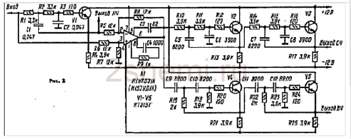
A scheme was used as it, which had been tested more than once before, which, with its simplicity and availability of parts, shows quite good characteristics. The scheme (like all subsequent ones) was once published in the Radio magazine and then published more than once on various sites on the Internet:
The input stage on DA1 contains a gain level switch (-10; 0; +10 dB), which simplifies the coordination of the entire amplifier with signal sources of different levels, and the tone control is directly assembled on DA2. The circuit is not capricious to some variation in the values of the elements and does not require any adjustment. As an op amp, you can use any microcircuits used in the audio paths of amplifiers, for example, here (and in subsequent circuits) I tried imported BA4558, TL072 and LM2904. Any one will do, but it is better, of course, to choose op-amp options with the lowest possible level of intrinsic noise and high speed (input voltage rise ratio). These parameters can be found in reference books (datasheets). Of course, it is not at all necessary to use this particular scheme here; it is quite possible, for example, to make not a three-band, but a regular (standard) two-band timbre block. But not a "passive" circuit, but with amplification-matching stages at the input and output on transistors or op-amps.
Filter block
Filter circuits, also, if desired, you can find a lot, since there are enough publications on the topic of multiband amplifiers now. To facilitate this task and just as an example, I will give here a few possible schemes found in various sources:
- the circuit that was used by me in this amplifier, since the crossover frequencies turned out to be just the ones that the “customer” needed - 500 Hz and 5 kHz, and nothing had to be recalculated.
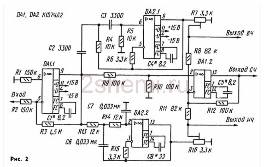
- the second scheme, simpler on the OS.
And another possible circuit, on transistors:
As yours already wrote, I chose the first scheme because of the rather high-quality band filtering and the compliance of the band separation frequencies with the given ones. Only at the outputs of each channel (band) were added simple gain level controls (as is done, for example, in the third circuit, on transistors). Regulators can be set from 30 to 100 kOhm. Operational amplifiers and transistors in all circuits can be replaced with modern imported ones (taking into account the pinout!) To obtain better circuit parameters. All these schemes do not require any adjustment, if it is not required to change the crossover frequencies. Unfortunately, I don’t have the opportunity to give information on the recalculation of these section frequencies, since the circuits were searched for “ready-made” examples and detailed descriptions were not attached to them.
In the filter block circuit (the first circuit of three), the ability to disable filtering for the midrange and high-frequency channels was added. For this, two push-button switches of the P2K type were installed, with which you can simply close the connection points of the filter inputs - R10C9 with their corresponding outputs - “high-frequency output” and “mid-range output”. In this case, the full sound signal goes through these channels.
Power Amplifiers
From the output of each filter channel, the HF-MF-LF signals are fed to the inputs of power amplifiers, which can also be assembled according to any of the known schemes, depending on the required power of the entire amplifier. I made UMZCH according to the scheme known for a long time from the Radio magazine, No. 3, 1991, p.51. Here I give a link to the "original source", since there are many opinions and disputes about this scheme about its "quality". The fact is that at first glance this is a class “B” amplifier circuit with the inevitable presence of “step” type distortions, but this is not so. The circuit uses current control of the output stage transistors, which allows you to get rid of these shortcomings with the usual, standard inclusion. At the same time, the circuit is very simple, not critical to the parts used, and even transistors do not require special preliminary selection in terms of parameters. In addition, the circuit is convenient in that powerful output transistors can be placed on one heat sink in pairs without insulating gaskets, since the collector leads are connected at the point " output", which greatly simplifies the installation of the amplifier:

When setting up, it is only IMPORTANT to choose the correct operating modes for the transistors of the final stage (by selecting resistors R7R8) - on the bases of these transistors in the "rest" mode and without load, the output (speaker) should have a voltage within 0.4-0.6 volts. The supply voltage for such amplifiers (there should be 6 of them, respectively) was raised to 32 volts with the replacement of the output transistors with 2SA1943 and 2SC5200, the resistance of the R10R12 resistors should also be increased to 1.5 kOhm (to "make life easier" for the zener diodes in the circuit power input op amps). The op amps were also replaced by the VA4558, and the “zero setting” circuit is no longer needed (outputs 2 and 6 in the diagram) and, accordingly, the pinout changes when soldering the microcircuit. As a result, when checking each amplifier according to this scheme, it gave out power up to 150 watts (for a short time) with a completely adequate degree of heating of the radiator.
ULF power supply
As a power supply, two transformers with rectifiers and filters were used according to the usual, standard scheme. To power the low-frequency band channels (left and right channels) - a 250-watt transformer, a rectifier on diode assemblies of the MBR2560 type or similar, and capacitors 40,000 microfarads x 50 volts in each power arm. For midrange and high-frequency channels - a 350-watt transformer (taken from a burned-out Yamaha receiver), a rectifier - a TS6P06G diode assembly and a filter - two capacitors of 25,000 microfarads x 63 volts for each power arm. All electrolytic filter capacitors are shunted with film capacitors with a capacity of 1 microfarad x 63 volts.
In general, the power supply can be with one transformer, of course, but with its corresponding power. The power of the amplifier as a whole in this case is determined solely by the capabilities of the power source. All preamplifiers (tone block, filters) are also powered from one of these transformers (it is possible from any of them), but through an additional bipolar stabilizer unit assembled on a Kren (or imported) MS or according to any of the typical transistor circuits.
The design of a homemade amplifier
This, perhaps, was the most difficult moment in manufacturing, since there was no suitable ready-made case and I had to invent possible options :-)) In order not to sculpt a bunch of separate radiators, I decided to use a radiator case from a car 4-channel amplifier, quite large, something like this:

All the "insides" were, of course, extracted and the layout turned out to be something like this (unfortunately I did not take a corresponding photo):

- as you can see, six terminal UMZCH boards and a pre-amplifier-tone block board were installed in this radiator cover. The board of the filter block no longer fit, so it was fixed on the then added aluminum corner structure (it can be seen in the figures). Also, transformers, rectifiers and power supply filters were installed in this "frame".
The view (front) with all the switches and controls turned out like this:

Rear view, with speaker output blocks and fuse box (since no electronic protection circuits were made due to lack of space in the design and in order not to complicate the circuit):

In the future, the frame from the corner is supposed, of course, to be covered with decorative panels to give the product a more “tradeable” look, but this will be done by the “customer” himself, according to his personal taste. But in general, in terms of sound quality and power, the design turned out to be quite decent. Material author: Andrey Baryshev (especially for the site website).
DIY preamplifier- I recommend to radio amateurs a circuit of a simple and at the same time high-quality sound power with a built-in timbre block. The preamp is built on the basis of the well-known two-channel operational audio amplifier LM833.
The working area of the microcircuit is implemented according to the scheme of a non-inverting amplifier with serial negative voltage feedback, and the unused area is assembled according to the repeater scheme, that is, it is simply muffled. The effective bandwidth of this circuit is in the range from 0.6 Hz to 18 kHz. The approximate gain is in the range from 0.9 to 110 based on the set trimmer values.
The LM833 dual op amp was originally developed for high quality audio applications. Such, for example; like pre amps and filters that can't work without a bi-polar power supply. The circuit of this device is capable of operating with supply voltages in the range from ±6v to ±18v, while the coefficient of non-linear distortion (THD) is only 0.002%. The peak voltage gain of the LM833 op amp reaches 112dB with a rated current of 6mA.
Preamp circuit
Any other two-channel op-amp can be used as an operational amplifier.


 How to distinguish rechargeable batteries from ordinary ones")


