A car alarm is an effective security system. It is often used on modern cars. Perhaps the alarm will not save you from theft, but it will help stop attempted damage. It often happens that in yards, children, accidentally or not, can hitch a car. Shooting of cars with pneumatic weapons is also common. With the help of a security system, the owner will be able to respond in a timely manner to the damage caused. An alarm can scare off criminals - there are many such cases. It is best to entrust the alarm connection to experienced specialists, but if there are none, you can try to do it yourself. The operation is not that complicated. Let's see how to connect the alarm.
Standards and schemes from different manufacturers
If we analyze the connection diagrams for car alarms from various manufacturers, we can conclude that there are no standard schemes or a single unification. Wires of the same color from different manufacturers solve different problems.
A specific brand has its own method of installing and connecting devices.
Installing an alarm unit
The first step is to install the main unit. The main problem for many is where to connect the alarm? It is installed inside the car, in a place known only to the driver. If this is a serious security complex, then there are several such blocks - it is best to place them in different places. This will help gain time when the car is taken over by car thieves. Before connecting the alarm sensor, you need to disassemble the left pillar. It is recommended to install it there.
Typically, a simple alarm unit is hidden inside the dashboard, but you can find other places. It is advisable to fix the block. It can be glued with double-sided tape or attached with self-tapping screws. Also at this stage, you should understand the electrical diagram - it shows how to connect the alarm to power, turn signals, and central locking solenoids.
Pulling wires
There are usually a lot of cords. It is better to stretch them in closed places, reliably protected from moisture and high temperatures. It is better to pull the wiring in a braid, and it is recommended to use plastic clamps for fastening to the body. They need to be tightened at a distance of no more than 20 centimeters from each other. Whatever the alarm system, it has redundant wires. The door and trunk release switches are different wires. But since the function is the same, they are connected via one cord. It's better to cut the second one. Subsequently, when any problems arise with the alarm, it will be easier to determine the possible cause and find the circuit in which there is a malfunction. The practice of installing alarm systems shows that complete wires are often not enough. Therefore, it is better to purchase additional ones in advance.
Power connection
Everything is simple here. Just find a large thick cable on the car's fuse box - this is the positive wire. The mass is taken from the body. The wires are stripped and connected using quick-release terminal blocks.

Alarm connection points
Let's look at popular connection points. The main plus for power can be found in the ignition switch. The starter contact with negative polarity is also located in this location. The ACC element is located there. An ignition contact with positive polarity can be found in the contact group of the lock.

In most cases, a standard lock is connected via a negative wire. But there are exceptions. The doors and their limit switches are controlled by positive polarity, but it is better to double-check everything according to the diagram. The gauges are connected to the positive wire, and the locations of these wires are marked on the fuse box. In most cases, these points are enough to solve such a problem as connecting an alarm system to a VAZ (whether it is a “Classic” or a modern “Vesta”).
Connecting external light signals
In almost all devices, the indication is carried out through the direction indicator lamps. It is better to use two wires - each is responsible for its own side. It is advisable to connect via diodes to prevent shorting the sides. It is more rational to connect through dimensions - they have lower power consumption, and also for connection you need one wire without diodes.
Connection to central locking
Perhaps the alarm system will not save you from it, but it will make the driver’s life more comfortable. Many systems implement central locking control. Let's see how to connect locks to an alarm system. We will assume that the solenoids are already installed.
The first step is to understand the colors of the wires and what commands they carry out. For this it is better to use a multimeter. The algorithm for finding the desired contact is quite simple: the device is set to resistance measurement mode. The minus is connected to one of the contacts, the button is pressed, which closes the door. Use a multimeter to look for zero resistance. After this, the button can be released. When the resistance is infinity, this is the desired contact. They are also looking for a second contact. This is done in a similar way.

Then the driver's side sill is removed. Next, find the necessary wires that were determined in advance. Alarm wires responsible for opening and closing doors are connected to them.
How to connect the Starline alarm system?
The Starline company produces popular modern security systems with an autostart function, as well as “quick dialogue” functions, which eliminate the possibility of hacking the security complex with a code grabber. Most models have 60 or more standard and programmable features.

For installation you will need an alarm system, a solenoid on the driver's door, a soldering iron and soldering materials, protective diodes, and electrical tape. Before connecting the alarm, remove the plastic of the steering shaft, unscrew the dashboard mounting screws, as well as other nuts and screws. Then an LED is installed in the windshield pillar, as well as a shock sensor. A service button is installed anywhere. These security systems have an antenna. It is better to mount it on the windshield. Next, connect the wires from the 18-pin connector according to the instruction diagram. So, the black wire is connected to ground, the red wire to positive. And further according to the scheme.
How to attach a keychain?
In addition to the fact that the driver is faced with the task of installing an alarm system, he must solve another problem - how to connect. Sometimes they are unprogrammed. A key fob or radio transmitter is the main device that allows you to control the security system. If the alarm is new, then reprogramming is not necessary. If the car is used, then it is better to reprogram it.

To begin with, the unit is put into service mode, which allows for maintenance of the device. To enter this mode, there is a special combination of pressing certain buttons - each manufacturer has its own.

First you need to disarm the alarm. The Valet button is pressed several times and then the ignition is turned on. If you hear several beeps, you have succeeded in logging into the system. Next, you need to press several buttons indicated in the instructions, after which a beep will sound. The key fob is programmed, and the system remembers it. You can use the alarm freely.
Conclusion
Here's how to connect the alarm yourself. In general, the process is simple and does not require special skills, but it is not always possible to set everything up correctly on your own. If your car has a lot of electronic systems, it is better to trust the professionals. But you can connect a simple budget system yourself, in half a day without experience.
Today, for many people, a car alarm is not only a security system that prevents car theft, but also a device that allows you to conveniently operate the car. An alarm system such as the Alligator has a number of additional functions (automatic engine start, opening windows, trunk, etc.), which undoubtedly please the car enthusiast and provide maximum comfort from use.
Installation of car alarm Alligator: basic elements
ATTENTION! A completely simple way to reduce fuel consumption has been found! Don't believe me? An auto mechanic with 15 years of experience also didn’t believe it until he tried it. And now he saves 35,000 rubles a year on gasoline!
The Alligator alarm installation scheme is based on the same principle as similar security systems, and if you know some technical features, you can install it yourself. The Alligator alarm is set up in accordance with the basic provisions of the instructions. But it is best to turn to specialists for help. Setting up Alligator by specialists will help you avoid problems with the system.
The main alarm unit Alligator is installed under the dashboard. The limit switch serves to ensure the safety of the hood, so it is attached under the hood of the car. When the hood is in the closed position, the free play of the switch rod must be at least 6 mm. Installation of the Alligator limit switch on the trunk is carried out in a similar way.
It is advisable to install the Alligator alarm siren under the hood, but it is important that no moisture gets on it.
This is due to the fact that moisture can cause oxidation of the contacts, which will lead to certain difficulties in operation. That is why it is advisable to additionally provide the siren with material that prevents water from falling into its elements. Also, do not place the siren near parts that can become very hot. A special bracket serves as a fastening device for this element of the Alligator car alarm.

Connecting the Alligator alarm: additional elements
The LED indicator is usually located in one of the upper corners of the windshield. The indicator is usually attached using double-sided tape. But if you want to fix the element on the dashboard, you will need to first drill a hole in it with a diameter of 7 mm.
The shock sensor is best placed on the hard surface of the bulkhead that separates the passenger compartment from the engine compartment. Installation of this Alligator alarm element is carried out using 2 screws; in addition, the device must be placed so that you can then get to its adjusting resistors. It is very important to position the Alligator temperature sensor correctly.
It is best to mount the temperature sensor under the hood. It is definitely worth considering that the temperature sensor must be attached to the rubber part of the radiator.
This is due to the fact that this sensor can respond not only to changes in the temperature of the coolant, but also to the indicators of metal elements. Secure the temperature sensor using zip ties.
It is advisable to install the Alligator transmit-receive module in the windshield area. This is necessary to ensure maximum communication range. Under no circumstances should this module be installed on side stands, as exposure to strong vibration may disrupt the operation of this device. If the windshield is treated with a reflective coating, the Alligator sensor can be placed in the rear of the car. The transceiver sensor is attached using adhesive tape.
Alligator alarm connection diagram - bottom contacts
The bottom row of the alarm connector is responsible for connecting the main elements. The connection diagram is as follows:

Alligator alarm circuit: rules for connecting the upper row of contacts
The top row is responsible for connecting additional control elements. The connection diagram for a car alarm like Alligator is as follows:
- White contacts (2 pcs.). These wires connect to the turn signals;
- White contact with black stripe. Responsible for controlling a six-tone siren. Combined with the red contact of the siren. In turn, the black cable of the siren joins the “ground”;
- The 12V red cable comes from the Alligator car alarm unit. Connects to the positive terminal of the battery. The connection must be made through a 15 amp fuse;
- The 12V white-red contact comes from the main alarm unit. Attached to the red contact of the main unit;
- Black-green, white-blue, dark green, white-green and red-green contacts are used to connect car alarms with integrated lock control relays in car doors.
The purpose of the following alarm connectors from Alligator:
- 4-phase black connector;
Black is used to connect to the transceiver.
The white one is attached to the shock sensor.
- 2-phase connector;
White connects to the alarm indicator;
Blue is attached to the “Valet” service button.
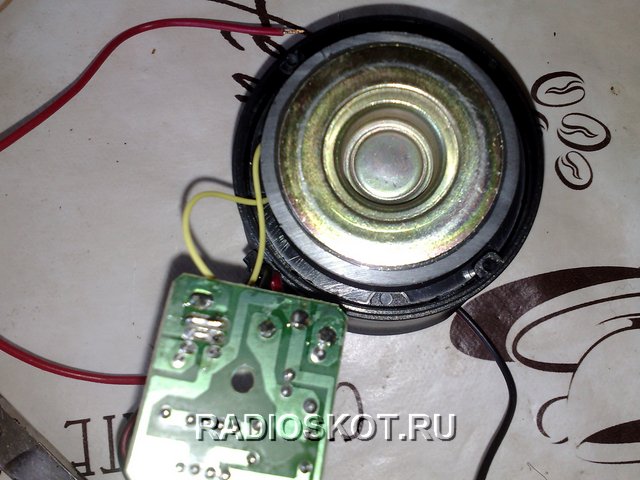
The idea of creating a laser alarm system was not new, but I just couldn’t find the time to assemble it. And now the weekend has finally arrived. A ready-made, simple car alarm was purchased at the store for $3. A compact piezoelectric head, inside of which the electrical alarm circuit itself is assembled.
When connected to a power source, the alarm makes a very high-pitched sound that resembles a police car.
So, the task was to make a sensor for an alarm. The transmitter is a laser diode. A simple red laser pointer ($1) was also purchased from the store, then the diode with optics was removed from the factory body of the device.
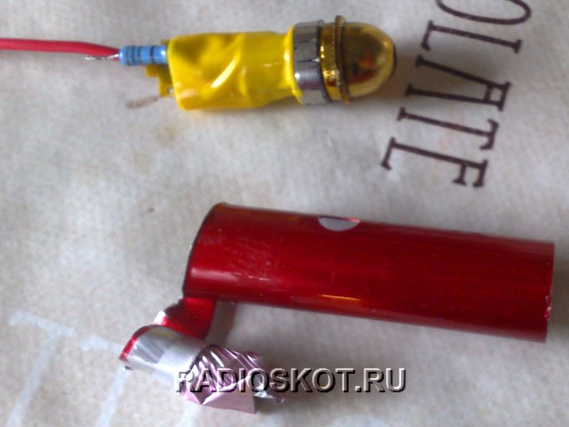
The laser button was unsoldered.

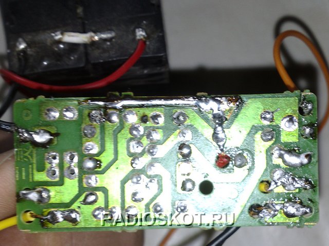
The minus of the laser diode is connected directly to the power source, and the plus is connected to the power source through a 30 ohm limiting resistor. The power source is a switching power supply from a DVD player, since the unit produces the voltage we need 6 volts.

The photodiode is used from a KODAK camera. The circuit is designed in such a way that in the presence of light, the photodiode does not allow the transistors to open, since its resistance is greater than the resistance of the 100K resistor, therefore current will flow through the photodetector. See the figure for the electrical circuit of a simple alarm (click to enlarge).

As soon as the lighting weakens or disappears altogether, the resistance of the photodiode increases and current begins to flow through the 100K resistor to the base of the first transistor and the junction opens, after which the second transistor opens to the collector of which the alarm is connected. After the alarm is triggered, the relay instantly turns off the laser diode, this is done so that after the lighting is present, the alarm will not turn off until you turn it off yourself.

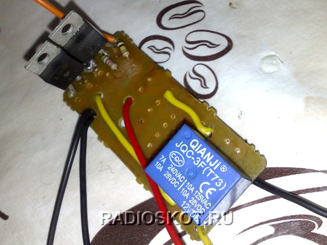
Any relay will do; I used a relay from an imported voltage stabilizer without any modifications.
It must be taken into account that the photo and laser diode must be at the same level so that the laser beam illuminates the photodiode; the latter must be in a dark case, since sunlight interferes with the correct operation of the device. Sensitivity to light depends on the value of the 100K resistor; as its resistance decreases, the sensor will be more sensitive.
The distance between the laser diode and the photodetector can reach several meters. When an object passes through the sensor activation zone, for a moment the laser beam falls on its body and does not illuminate the photodiode, at this moment an alarm is triggered and the laser is simultaneously turned off so that it does not illuminate the photoresistor later. This sensor can be used as a sensor to turn on the yard light, you just need to install a second relay instead of the alarm, which will turn on the light.
Discuss the article ALARM ELECTRICAL DIAGRAM
Currently, for many people, a car alarm is not only a means of protecting the car from theft and hacking, but also a device used for the comfortable operation of the car. (opening, closing doors, windows, trunk, turning on/off lights in the cabin, etc.) In this article, I would not like to focus on how a car is stolen, what methods and techniques are used, from bricks to highly intelligent equipment.
I would not like to talk about non-standard solutions when connecting an alarm system, to prevent undesirable situations, at the beginning of writing this article the goal was to combine and unify all knowledge on connecting an alarm system in a car according to a standard scheme, to facilitate the installation and maintenance of security units in your cars, and not bring out a panacea against theft.
1.1 Standard of various alarm manufacturers
Unfortunately, after studying a number of car alarm connection diagrams from various alarm manufacturers (Mongoose, Alligator Sheriff, Tomahawk, Pantera, StarLine, Scher-Khan, etc.), I came to the conclusion that unified unification for alarms (security systems) No. That is, terminals with the same markings and colors from alarm systems from different manufacturers have different functions during operation. Apparently this refers to the still ongoing “battles” in the manufacturers’ market for their own standards. The assumption that this discrepancy is possible due to security is rejected due to the fact that the alarm is installed inside the cabin and in a hard-to-reach place and this is its priority barrier from burglars, and not the use of wires of different colors for the same functions.
In addition, it should be noted that another well-known fact is that burglars never try to figure out what kind of alarm system is installed and how it works. The most important thing is to neutralize it, turn it off and then simply force the car to start, without restoring the standard wiring and functions, but using redundant methods (bypass wires, etc., this is much easier)
Once again, I repeat that the article is intended for ordinary people who want to service the car alarm system on their own (installation and operation), therefore, further, according to the purpose of the article, the basic techniques for mounting and installing alarm components will be given. The appendix will contain an archive of diagrams for connecting car alarms (this archive will be constantly updated whenever possible, thanks in advance to active readers who will send an electrical diagram for connecting an alarm and a programming table that is not available in the archive for posting on the site).
1.2 Methods for wiring and placing wires in the door-body opening when installing an alarm
When installing solenoids in the doors and extending wiring to them, the most problematic area from the alarm becomes the place where the wires are constantly bent, namely in the opening where the doors are hung from the body.
On domestically produced machines, the most suitable option is the use of rubber feed-through tubes, which are fixed at one end in the rack, and the other end freely passes through the hole in the door. (Figure 1A) In this case, the wires are reliably protected from external influences, the bending radius of the wires passing between the stand and the door is at least 100 mm, which ensures long-term reliable operation of the wire without fractures or breaks. A section of wire inside the car door is left with a reserve and secured. Currently, you can find different types of bushings on the market. Italian-made bushings are widely used. Unfortunately, they have one significant drawback: they are made of plastic. The tubes have good oil and petrol resistance, but at temperatures below -30 degrees they become brittle. In our conditions, for installation of alarm wiring, it is better to use domestically produced bushings made of frost-resistant rubber.
The S-loop method is used quite often. (Figure 1B) This method drills misaligned holes in the pillar and in the car door. The wires are passed in such a way that an S-shaped loop is formed. Variations on this theme are quite varied and depend on the level of reputability of the company and the professionalism of the installers. In the simplest case, bare wires are passed through the holes. It is good if rubber bushings are inserted into the holes, and the wires are enclosed in a PVC tube or wrapped with electrical tape. In more reputable companies, the wires are passed through corrugated rubber tubes, which are sometimes supplied with wires made in Taiwan. The disadvantages of this method include the fact that the wires work simultaneously to bend and twist. If this method is used on imported cars, where the gap between the pillar and the door is quite large, this is not important, since the bending radius of the wires in this case has acceptable values, and the twisting angle can be completely neglected. On domestically produced cars, it is better not to use this method, since the gap between the pillar and the door has minimal dimensions, and when the door is closed, the wires bend almost at a right angle. It is not difficult to imagine what will happen to the wires after several hundred doors are closed. In addition, corrugated rubber tubes made in Taiwan do not stand up to criticism in terms of rubber quality. It is clearly designed for the mild Taiwanese climate and cannot stand the test of our frosts.

Figure 1A Figure 1B
Methods for installing wiring in the body door connector when installing an alarm system.
1.3 Connection to the central locking and installation of alarm solenoids in the car doors.
When installing solenoids in the door cavity, the most correct solution would be to install them as far as possible, directly from the door opening/closing button rod, since the longest rod will compensate for the angular error of the solenoid relative to the door opening/lock button. 
Installing solenoids and connecting them, such problems are getting further and further away from us. Now perhaps the more pressing question is how to connect to the central locking system in a car.
So, using the example of connecting an alarm system to the central lock of a Toyota Corolla, model range 2006-2012, let’s consider this case.
First of all, you need to understand the colors of the wires responsible for certain commands. To do this, it is best to use a multimeter. We remove the handle with the central locking control buttons from the driver's door trim. See the article "Removing the Toyota Corolla door handle" The photo below shows a plug with already calculated central locking control contacts.
The algorithm for finding contacts is simple: switch the multimeter to resistance measurement mode, connect the ground of the device to one of the contacts, press, for example, the close button and look for zero resistance. After this, we release the button if the resistance becomes equal to infinity, this is our option, if not, then we continue the search, going through various combinations. We also find a second contact.
As a result, it turned out that the brown wire is common, yellow and blue are the output control signal. In this case, it is worth noting that the brown wire is negative, that is, the central locking is controlled by a “negative” control signal.

Next, from the driver's door, remove the threshold and the instrument panel cover. The mounting block opens in front of us, it is in it that we will connect to the plus for powering the alarm (the thickest wire is the power wire of the mounting block)

An example of connecting the alarm power supply is shown in the photo below. The alarm power wire is passed through the plug and secured with tape, then the plug is installed in its place.

At the bottom of the threshold, from a bunch of wires coming out of the doors, we find our yellow and blue wire, which we previously identified from the central locking control buttons on the door handle. We connect to them using clips (in the photo in red) the alarm wires for locking and opening the doors. Also, to confirm our research, you can look at the electrical circuit for unlocking the doors and interior lighting of the Toyota Corolla; the yellow wire is for opening, the blue wire for some reason is not shown in the conventional block of the front door I5.

We connect the negative wire of the alarm to the body, in principle, at this point the stage of connecting the alarm to the central locking is completed.
1.4 Installation and operation of limit switches (contacts) during alarm installation.
Electrics in a car are increasingly turning into electronics. The use of standard interior lighting switches is becoming increasingly problematic. If previously the circuit of limit switches for doors was carried out according to the scheme when the power supply of the interior lighting lamp was through a fuse and a limit switch, while the use of these limit switches for signaling ensured a clear alarm when connected to any of the contacts, now the indication unit is usually also involved in this connection scheme . When using this indication unit by connecting it to one of the limit switches, the following possible problems arise:
- influence on the display unit through internal alarm resistance;
- influence on the signaling through the internal resistance of the display unit;
- impossibility of connecting to only one contact, from one door, and not to all from each door (due to the problems described above);
- the use of diodes to prevent the problems described above.
As a result, the most optimal solution is the following:
- connection to the interior lighting through the interior lamp. The advantage of this connection is the only connection for alarm activation from any of the doors;
- connection at the door contacts, but using diodes.
1.5 Stretching wires in the car and duplicate wires at the alarm terminals.
It's no secret that when installing an alarm system, it is better to install wiring in closed, dry and protected areas of the body. It is optimal to use plastic clamps to secure and guide the wiring (Figure 3). 
Figure 3 (Clamps for fastening wires when installing an alarm system in a car)
1.6 Connecting an external alarm indication in a car.
In all the alarm systems I have encountered, the light indication of arming and disarming is carried out through direction indicators. In this case, two wires are used on the right and left sides with two diodes to prevent the sides from shorting through the alarm. I consider the most rational for light indication to be the use of dimensions; they have comparable power consumption compared to direction indicators, requiring the connection of only one wire without the use of diodes.
1.7 Connecting the trunk opening function through an additional channel. Using the additional channel (CH2)
Currently, almost all alarm systems on the market support the second channel. Using this channel on the alarm, you can connect to it any electronic device triggered by an impulse (for example, opening the trunk using a solenoid). From my own example, I can say that this is a very convenient function. There is no need to climb into the cabin every time to open the trunk, especially since the connection is not so difficult (Figure 4). As a rule, the alarm unit produces a negative pulse (apparently for safety reasons), and the solenoid is triggered by a positive pulse in the standard wiring; in this case, you cannot do without an additional relay. The pulse current usually ranges from 300-500 mA, so this is also an obstacle to connecting a solenoid without an additional relay.

Figure 4 Connecting the trunk opening function from the alarm.
Examples of mechanical installation of an electric trunk lock for some cars, with subsequent control from an alarm or from a button, can be found in the article “Electric trunk lock”.
1.8 Electrical diagrams for connecting an alarm system in a car.
1.8.1 Alarm connection diagrams - manufacturer Alligator (Alligator)
Alligator LX-440 Installation Instructions
Alligator LX-440 User Manual
4.69 Rating 4.69
Central lock (C.Z.)
Central locking is an electromechanical system for centralized locking of car door locks, which allows you to simultaneously close or open all car doors by turning the key in the lock of one door or using a remote control (key fob), which is built into the key or into a separate control key fob. Together with the doors, the system closes and opens the trunk and the fuel tank hatch, if it is equipped with a drive (actuator). If the car has electric windows, the central locking may have a “comfort” system that automatically closes all windows and the car’s sunroof.
Central locking is a complex system consisting of many components, and in order to connect an alarm system to it you need to have an idea. how it works and what it consists of.
Here we will look at how the central lock works, what types there are and how, depending on the type, to connect an alarm to it. Central locking diagrams and explanations will allow us to understand and shed light on the topic of connecting an alarm system to the central locking of a car.
Central locking device
The central lock consists of:
Central locking control unit
The central locking control unit is the electronic brain center of the entire system. Blocks can vary in complexity, from very simple to microprocessor-based and very complex. As a rule, the entire electronic part is placed in one housing with connectors, but with the advent of the CAN bus in modern cars, the control part can be divided into separate blocks scattered in different parts of the car.
The control unit monitors the state of door limit sensors (limit switches), contact groups of door locks, the position of the lock control buttons and other sensors. All sensors are connected to the block by wires through which they report their status and changes to the block, and it reacts to changes in incoming signals by controlling electric drives (actuators) through wires that lock or unlock the doors, trunk and gas tank hatch of the car.
In some cases, the Central Unit can also control the car's turn signals, flashing them when closing and opening doors. If this option is present, then you can connect an alarm to these wires to control the car's turning lights.
The control unit may also have a built-in receiver for remote control of the central locking system. This receiver can be located either inside or separately from the control unit and is connected to the unit with wires that can be used to connect the central locking alarm control.
I would like to note: If you find a unit in a car and it can do a lot, then we connect 80% of the alarm wires to it and all that remains is the siren and engine blocking! Well, also alarm sensors.
Input sensors and buttons
input sensors in the system are:
- door limit switches, they determine whether the door is closed in relation to the car body. The light in the cabin directly depends on the state of these limit switches and of course we connect them to the alarm system to protect the doors.
- microswitches in the lock design, they determine where the key in the door lock is turned and, depending on this, tells the unit to lock or unlock the doors. (Can be used to connect alarm)
- microswitch in the electric drive of the lock - it determines the current position (locked or unlocked), and is also used to control the central locking.
- The button used is a three-pin (with a common and two normally open contacts) two-way button; there are also two-pin or five-pin central locking control buttons. There may be one such button in a car on the driver's door or on the panel, or two on the left and right front doors. By pressing the button in one direction or the other, we let the control unit understand whether to lock or unlock the doors. The wires of these buttons can also be used to connect an alarm system. It should be noted that there may not be buttons.
Actuators (actuators)
Central locking actuators are mainly used electromechanical (hereinafter Electric Drive), but in the case of a pneumatic system, the actuators operate based on air pressure (hereinafter).
Electric drive
Electric door lock drives are available in several design options and differ in the value of traction force (from 2.5 to 6 kg).
All electric drives have a plastic housing with a built-in DC electric motor and a plastic (or metal) gearbox that converts rotational motion into linear motion. The direction of translational movement of the motor output rod changes when the polarity of the supply voltage changes, as a result of which the motor rotates in one direction or the other, thereby unlocking or locking the door lock. The most common electric drives are T-shaped (“pistol”) and square types.
There are electric drives with two electric motors, one closes/opens the lock, and the other blocks the ability to mechanically open the lock by pulling the handle inside the car or lifting the lock rod. Such electric drives are controlled by three wires (Classic example is BMW cars). In modern car designs, electric drives are built into the common door lock housing together with the mechanical part.
Electric drives of locks are controlled by pulse voltage lasting 0.8 -1.5 s. This time is enough for the locks to open or close. You cannot supply power to electric motors for more than this time, otherwise it will lead to their failure, in other words, they will burn out.
Electric motors differ in the presence or absence of a contact microswitch, mechanically connected to a retractable rod. The three wires of this microswitch are led out and together with the two supply wires of the engine itself and form the so-called five-wire electric drive, usually installed in the front doors. The microswitch built into them, together with the control unit, ensures that the two-wire electric drives of the rear doors are activated when the front door lock is manually unlocked/locked using a metal car door key or a lock control button.
Examples of electric drives for closing/opening car doors.
700 423
 351
386
351
386
 278
182
278
182
 645
432
645
432
Pneumatic drive
The pneumatic actuator consists of a plastic housing with a fitting for the air supply and an outlet for the rod; inside there is a rubberized membrane with a rod attached to it.
The operating principle is very simple. When air is supplied to the drive, the membrane is pushed up, and when air is sucked out, it moves down, moving the rod, locking or unlocking the door lock.
Pneumatic actuators also differ from each other in the presence or absence of a contact microswitch, mechanically connected to the retractable rod. The principle of the microswitch is the same as that of .
Some pneumatic actuators use built-in solenoids (an electromagnet with a movable core). These actuators prevent an attacker from opening the lock with a ruler, for example. When you try to raise the rod without the knowledge of the control unit, the microswitch is activated and the unit supplies voltage to the solenoid, while the solenoid core blocks the rod, preventing the door from being opened by robbery, and the compressor additionally creates a vacuum, returning the rod to the “closed” state.
Currently, car manufacturers have abandoned the use of pneumatic central locking systems and only use electric drives!
Let's sum up the interim results: We now know how the central locking of cars works, we have found out that it can be controlled in different ways: using the contacts of the central lock control button, the door lock contact group, the actuator contact group and, in some cases, the actuator power control wires. Next we will look at the Types of central locks and how to connect them to the alarm system so that it can control them. All connection diagrams are presented for alarm systems that have built-in lock control relays: three wires for closing and three wires for opening.
Types of central locking control
- Central locking control using a CAN adapter
- Installing a central lock if the car does not have one
Scheme Central locking control with positive potential
 410
336
410
336
On diagram-A shows a car central locking with an electronic unit and a positive control signal. This type of control is typical for cars from General Motors Corp., Renault, Chrysler, BMW (E39, E34, E38), VW Passat and some Ford models.
To control such a lock, it is enough to apply a positive, short pulse of 1 s to the control wires, Block C.Z. will react and close or open the door locks accordingly. The control is low-current, if you connect the control with a crocodile to +12 volts, and pierce the wires in the harness at the exit of the driver's door with a sharp probe, then when it hits the desired wire, the locks will work, so you can find the necessary control wires. The diagram shows an example of connecting an alarm system to control a central locking system with a plus control; in principle, the alarm system simulates pressing a button in one direction or the other to close or open the central locking system.
On diagram-B shows the central lock of a car, which does not have an electronic part and is controlled by the positive potential of the drive itself using a contact group inside it. There can be several control locks, for example Two - the driver's and front passenger doors. Such central locking systems are used in some FORD cars after 92.
The operating principle is brilliantly simple. The motors in the drive rotate in one direction and have 2 rest points, one is closed - the rod is pulled into the drive as much as possible, and the state is open - the rod is extended out of the drive as much as possible.
Scheme Central locking without electronics with positive control
 410
336
410
336
The diagram shows the state of the locks in the open state. If you close the control door, for example, with a key, the door will close mechanically and the contact group inside will switch, causing +12V voltage to appear on the contact ( L)(Lock-Close), all other drives are open and the motors are connected to this wire through their own contacts. As a result, the engines turn on and retract their rods, closing the locks.
When the rods retract, the internal switches will operate and disconnect the motor from the contact ( L) and connect it to the contact ( U)(Unlock-Open). As a result, all the locks are closed and the system is in equilibrium. Now if you apply positive voltage to the contact ( U), the motors will start moving and open the locks, the motors will switch to contact ( L) and the system will be in equilibrium again.
On diagram-B shown. how to connect the alarm relay contacts. so that she controls such a central lock. The time must be set to 4 seconds so that the drives have time to close/open. The power supply to the alarm relay must be connected through a fuse.
A: Reversible lock control using power buttons
 425
346
425
346
On diagram-E The car's central locking is shown with reverse control from power buttons installed in the driver's and passenger's door trim and does not have an electronic control unit. This method of drive control is used on some cars produced in the 90s, mainly American: Chrysler, Ford, Chevy Cavalier, etc.
If you look at the lock control button installed in the driver's door, there will be five wires coming from it: one wire with constant +12 V power, two wires with constant ground, and two wires with ground in the initial state. When you press the button in one direction or the other, the negative potential will change to positive on one or the other wire. when locking on the locking wire, when unlocking on the unlocking wire. In this case, electric drives will close or open the car door locks.
The diagram shows how the alarm wires need to be connected to control such a lock. Essentially, connecting the alarm relay contacts copies the button in the passenger door. During installation, you must be especially careful, because incorrect connections will lead to immediate damage to system elements. As protection, it is necessary to use a 10-15 A fuse in the +12 V power circuit.
B: Reversing control with central locking unit
 425
346
425
346
On scheme-F shows a method for connecting an alarm system for direct control of electric drives in the presence of a central locking control unit.
This control is suitable for almost any type of central lock except vacuum and provided that with mechanical action on the lock rod, handle or door latch, all locks close and open. Only in this case will there be a guaranteed closure of all doors, and not just one.
It is ideal to connect if the control unit is a separate unit and the outputs to the electric drives are common. In this case, we find the control unit, determine the power wires and, as in the diagram, cut them and connect the wires from the alarm into the gap.
It is important not to confuse the connection, otherwise you can damage the relay and alarm tracks or central locking unit. Let's remember the main rule of reverse control - the general contacts of the control relay from the alarm are always connected towards the drive.
If the lock control is built into the Common Unit, then the power wires for the drive control often come out of different connectors, which complicates the task somewhat. In this case, we can apply such a connection to one of the electric drives of the car's control doors. For example: We find the power wires going into the driver's door. This can be done using a car control:
- We hang the crocodile on the ground, pierce the wire with a probe and close/open the lock using the original remote control or the car lock control button. On the wires we need, the control light will flash.
- Thus, we find the two wires we need and to make sure that these are the right wires, we hang a tester on both wires, on one crocodile. to another probe, to which one, it doesn’t matter. When opening and closing the door lock, the control lamp should flash in time with the operation of the electric drive.
- We cut the closing wire, now when the central lock is activated, the drive should be silent and not show signs of life, both in opening and closing.
- For a short time, you can apply +12 Volts to the cut wire leading into the door through a 5A fuse. The electric door drive should close and the entire central locking system should operate.
- If this happens, then cut the second wire, and temporarily connect the first. We briefly apply +12 V towards the door (drive) and the drive should operate and open its own door first, and then all other locks should open.
- If all is well, then we connect the wires from the alarm to the breaks in both wires according to the diagram presented here. It is important not to make a mistake and carefully check the correctness of your connection.
Attention: When searching and checking the wires, the lock pawl must be latched and the door button is disabled or pressed for everything to be correctly emitted - the doors are tightly closed and there is no key in the ignition.
C: Reversible control of electric drives
 425
346
425
346
On scheme-G shows how to switch alarm relay contacts for direct control of the lock's electric drives via two wires by reversing the potentials on them.
In the initial state, there is a negative potential of -12 Volts on both wires; it gets there through the normally closed contacts of the closing relay and the unlocking relay.
When a signal is received from the key fob to arm, the locking relay is activated and disconnects the common contact from the negative and connects it for 1 second to a normally open contact which has a positive potential of +12 Volts, and then the common contact returns to its original state. This time is enough for the motor, rotating in one direction, to retract the drive rod inside the housing and the locks close.
When a signal is received from the key fob to disarm the system, the unlocking relay is activated and disconnects the common contact from the minus and connects it for 1 second to a normally open contact on which there is a positive potential of +12 Volts, and then the common contact returns to its original state. This time is enough for the engine, rotating in the other direction, to push the drive rod out of the housing and the locks to open.
This connection diagram is applicable in the case when the car does not have central locking or electric drives. We connect self-installed electric drives in doors according to this diagram.
If the Control Unit breaks down, you can disconnect all drives from it and connect them to the alarm using this diagram.
Central locking control with pneumoelectric compressor
This type of central locking system uses an air compressor to operate the locks and is used in Mercedes Benz, Audi, Volkswagen vehicles.
Central locking of a Mercedes Benz car - 124 body.
Let's consider connecting an alarm system to a pneumatic lock, using a car as an example. Mercedes Benz - 124 body - diagram-H. This car has a classic compressor and pneumatic actuators. Pneumatic actuators with three contact switches are installed in the driver's and front passenger's doors, as well as in the trunk lid.
 410
336
410
336
- Battery
- Ignition switch contact group
- Fuse box
- Connection block
- Warning buzzer switch
- Block C.Z. with Compressor
- Contact group of the right front door drive
- Trunk drive contact group
- Contact group of the left front door drive
The principle of operation is ingeniously simple - if all the locks are open, then the central wires on the contact groups of the drives (according to the scheme 7,8,9 - green, yellow, blue) are closed to +12V and the System maintains balance. When there is a mechanical impact on the rod, for example, by turning a key or pressing a rod with a plastic tip, we close the door and the central wire of the corresponding contact group switches to ground (-12V). The unit reacts to the change in potential and understands that one door has closed and the others need to be closed - the electric motor with the pump turns on and pumps out air from the door drives, as a result the rods of all drives lock the locks. and the central wires of all contact groups are shorted to ground and the system again goes into a state of equilibrium - the locks are closed. As soon as the door or trunk is mechanically opened, the control wire closes to positive again, the compressor turns on and pumps air into the drives, as a result the rods extend and all the locks come off. The system returns to a state of equilibrium - the locks are open.
 410
336
410
336
To connect the pneumatic central locking you need to find any of the three control wires in the car, cut it and connect the two wires from the alarm to scheme-I. It is more convenient to use the driver's door wire (blue diagram). He leaves the door and goes down the left threshold.
We connect the alarm relay contacts according to the diagram presented here. This connection ensures free passage of the signal from the driver's door to the compressor through the alarm relay contacts. In other words, we do not interfere with the correct operation of pneumatics.
When arming the alarm system, the locking relay of our alarm system is activated, as a result General the contact of this relay opens normally closed contact, "breaking" the control wire from the door and connects to the normally open contact connected to -12V. Thus, the alarm commands the compressor to close the doors.
Due to the fact that the pneumatic system is inert and it takes 1.5 to 3.5 seconds to lock all the doors and the control wire contacts switch to negative, we need to ensure that the alarm relay is held during this process so that everything works as it should. The signal time for the central locking alarm control must be set to 4 seconds. Almost all alarms have this option; you need to study the instructions and select the desired time (4 seconds).
If this is not done, then as soon as the alarm relay returns to its original state, the circuit between the drive control wire and the compressor will be restored, and if by this time the lock has not yet closed, then there will be a positive on the control wire and the compressor will receive a command to open everything. As a result, the alarm system was armed and the doors remained open.
It’s the same with disarming, only in the process the unlocking relay of our alarm system is involved and it interrupts by supplying plus 12 volts towards the compressor, which starts the process of opening all doors.
Attention: It is very important not to confuse the two alarm wires connected to the control wire break. If this happens, then when the relay is turned on, a short circuit occurs, and these are knocked out fuses, burnt out track alarms and a stuck relay in it. The alarm needs to be repaired or replaced with another one, so be very careful when connecting, we give the voltage towards the compressor and not otherwise!!!
 220
169
220
169
To complete the “picture”, consider the central locking of the VW GOLF III. In this example, we will see that the control of the compressor lock can be not only classic like that of the 124th, but also mixed.
The picture on the left shows the structure of the VW GOLF III central locking system.- Pneumatic drives for interior doors
- Pneumatic drive for trunk lid and fuel tank flap
- Compressor central locking
- Air tubes connecting the compressor with pneumatic actuators
The thing is that in Golf 3 you can control the central locking two ways.
 180
240
180
240
Note: If the lock is closed using the gray wire, it cannot be opened using black-red the wire. If we use it for control grey And green wires, then if there is a key in the ignition, you cannot lock the car using the alarm key fob.
When connecting the alarm to the central locking of the Golf III, the second method is preferable. The wires come out of the door and are in the same connector. like the black-red wire, the picture shows how the wires from the alarm are connected to them. To make sure that these are the wires we need, snap the lock pawl so that the rod in the driver's door can lower freely, take the car control, connect it to +12V with a crocodile hook, and pierce the gray wire with a probe, the compressor motor should fire and close the doors. We pierce the green wire with the control, the compressor motor should work and open the doors. Alarm outputs for controlling the central locking are switched according to the diagram.
In addition to this, if you want the windows to close automatically when arming, then you need to connect the alarm wire - (window control) to brown-gray wire. This wire comes to the comfort unit, which is installed behind the left kick panel in the driver’s feet and looks like a dual relay in one housing. Control via this wire is carried out by a minus and withholding the signal (as long as the minus is present, the windows rise, turn off the minus - the windows stop).
Central locking control via one wire with positive potential
On scheme-K And scheme-L shows a car's central locking system with positive potential control over one wire. This single wire provides both locking and unlocking. Control on it is achieved by changing the level of positive potential. The required level of the positive signal is set by a resistor, through which it is supplied to the control wire.
This type of control is used on Dodge Stratus 1995, Ford Probe, Chrysler, New Yorker, Concorde, LHS, Eagle Vision 1993-1995.
 410
336
410
336
Ford Probe
- The Ford Probe control wire is located under the left kick panel trim and is green and black in color. Signallocking- positive pulse +12 V. Signalunlocking4.7 kOhm.
- Connecting the alarm system scheme-K.
 410
336
410
336
- Chrysler Cirrus 1995(White-green wire);Dodge Stratus, Chrysler New Yorker, Concord, LHS, Eagle Vision, 1993-1995.(Orange-purple wire)
- Signal locking- positive pulse +12 V, connected through a resistor620 Ohm. Signal unlocking- positive pulse +12 V, connected through a resistor2.7 kOhm.
- Connecting the alarm system scheme-L.
Control of central locking via one wire with negative potential
On scheme-M And scheme-N shows a car's central locking system with negative potential control via one wire. This single wire provides both locking and unlocking. Control on it is achieved by changing the level of negative potential. The required level of the positive signal is set by a resistor, through which it is supplied to the control wire.
This type of control is used on some Mazda, Dodge Caravan, Plymouth Voyager, Chrysler Town & Country 1996 vehicles.
 410
336
410
336
- Car Control Wire1996 Dodge Caravan, Plymouth Voyager, Chrysler Town & Countryis located under the casing on the left on the “BODY” connector of the block and is White in color with a light green stripe. Signal
- Car central locking controlMAZDA(White-green wire)
- Signal locking- negative pulse -12 V, connected through a resistor1 kOhm.
- Signal unlocking- negative pulse -12 V.
- Connecting the alarm system scheme-N.
 410
336
410
336
Some Nissan and Mazda vehicles use single-wire control. where the unlocking signal is a negative pulse of -12V, and locking is achieved by “breaking” the control wire.
For example, on a 1991 Mazda MPV, the color of the control wire is Green-White, which can be found in the lock control module connector behind the glove compartment.
On 1991-1995 Nissan vehicles, this wire comes out of the driver's door and may be orange/blue or orange/black, brown or brown/black, depending on the year and model.
You can find this wire using a car tester. “Hang the crocodile” to minus, latch the driver's door lock pawl, turn off the limit switch so that the car does not see that the door is open, and close the central locking with the key. We pierce the suspected wire with a control probe and if this is it, then the central locking will work and all doors will open. To finally make sure of this wire, let’s cut it, C.Z. should work and the doors should close. If everything is so, then we connect the wires from the alarm system to the wire break. scheme-O. The duration of holding contacts on the alarm is 1 second.
Central locking, connecting the alarm to the central locking.
Central locking. Connecting the alarm to the central locking.
Msvmaster Latvija, Riga +371 29675090 290
83
290
83


