EXCITATION SYSTEMS FOR SYNCHRONOUS MOTORS OF THE VTE, VTP SERIES
Thyristor exciters of the VTE, VTP series are designed to power the excitation windings of synchronous motors with a power of up to 12500 kW, with automatically controlled direct current, during their direct and reactor starting, synchronous operation and in emergency modes.
The exciters meet the requirements of GOST 24688-81, GOST 18142.1-82 and can be used instead of rectifiers of the TV-320, TV-400, TV-600, TVU, VTE-320, TE8-320, V-TPE8, V-TPP8, KTES series .
Exciters are produced for rated currents of 200, 320, 400, 630, 800 and 1000 A, rated voltages from 24 to 300 V. Exciters for currents of 200, 320 and 400 A are naturally air cooled, and for currents of 630, 800 and 1000 A - forced air from built-in fans.
ADVANTAGES OF USE
easily reprogrammable when setting up the structure of automatic control systems;
stabilization of excitation current in manual mode;
stator voltage regulation;
cos regulation? at the load node;
stator reactive current regulation;
two-wire interfaces for external automation and diagnostics;
automatic testing mode before switching on;
checking surge protection circuits;
checking the serviceability of power circuits.
extensive protection system;
built-in diagnostic system and recording of the “accident trace”;
any object orientation at the Customer's request.
DEVICE
Power supply of VTE, VTP (hereinafter referred to as “exciter”) can be provided from one input voltage of ~380 V, 50 Hz. It is also possible to power the controls from a separate input. To control the on and off circuits of oil switches, a voltage input = 220 (110) V is provided. The layout and composition of the relay switching part of the exciter is determined by the requirements of the specific application.
The exciter rectifier is made according to a three-phase bridge circuit with one thyristor in the arm. In parallel with the load (excitation winding of a synchronous motor), a starting resistance is connected through a contactless switch on thyristors, designed for asynchronous starting and reducing to an acceptable value the overvoltages that occur in the rotor winding during asynchronous engine operating modes. Moreover, the switch thyristors are switched on both from the microprocessor control system in the start-up mode and directly from overvoltages occurring on the excitation winding.
The microprocessor control system controls the entire complex of exciter equipment, from receiving external and internal discrete and analog signals to issuing control potential and pulse signals, as well as indicating all operating modes of the exciter using the built-in remote control terminal (PT).
Before switching on the exciter to the operating mode, a testing mode is performed, during which the following is checked:
serviceability of the rotor overvoltage protection circuits by supplying voltage pulses of real magnitude and recording the activation of the switch thyristors in both directions;
serviceability of the converter and external power circuits.
The exciters have operating modes of automatic and manual control of the excitation current. Switching from mode to mode is carried out without turning off the exciter by a switch installed on the converter door. Measuring instruments (stator current, excitation current, excitation voltage, cos ?) and a remote control terminal are also installed there, with the help of which you can select the structure of the automatic control system, change the parameters of the regulators and settings of the control and protection system. The same procedures can be carried out using a PC, for which a set of service software has been developed that significantly facilitates and speeds up the setup process.
In manual control mode, the exciter provides:
automatic supply of excitation in the rotor slip function in the range of 1-5% with the selection of the optimal half-wave of the rotor current for direct or reactor starting of a synchronous motor;
excitation voltage adjustment in the range from 0.1 to 2.0 nominal;
limitation of excitation voltage to a minimum from 0 to 0.5 rated, excitation current to a maximum of 1.75 rated;
forcing the excitation voltage with a factor of at least 2.0 rated at the rated voltage of the supply network and a “boosting” current with a factor of 1.75 rated;
limiting the rotor current during overload according to the time - current characteristic;
protection against internal short circuits in the converter, against external short circuits on the DC side;
field suppression during normal and emergency engine shutdowns by switching the converter to inverter mode;
protection of a synchronous motor from loss of excitation and from prolonged starting with an operating time of up to 30 s. In the automatic control mode, the exciter, in addition to the above, provides automatic regulation of the excitation current based on the stator voltage, cos ? in the load node or stator reactive current.
LEGEND STRUCTURE 
GENERAL INFORMATION ABOUT THE DESIGN
Structurally, the exciter is made in the form of a cabinet with two-way service. Controls, measuring instruments and alarm lamps are located on the cabinet door. Thyristor cooling is natural or forced (VTE, VTP) air. External connection cables are supplied through holes in the bottom of the cabinet, sealed with sealed leads. Brackets are provided for securing cables. The power converter transformer is installed separately.
Dimensions of the VTE (VTP) cabinet (WxHxD) mm. – 800 (1000) x 2000 (2150) x 600.
BASIC TECHNICAL DATA
Table 1. Basic technical data of synchronous motor excitation systems
| Parameter name | Meaning |
| 1. Input supply voltage three-phase, V | 380 +10/-15 % |
| 2. Input voltage frequency, Hz | 50 ± 2% |
| 3. Voltage boost ratio, oh. e. | 2.0 Un |
| 4. Current boost ratio is not less than, p.u. | 1.75 In |
| 5. Operating voltage DC, V | 220 (110) +10 /-15 % |
| 6. Efficiency, not less | 0,95 |
| 7. Degree of protection | IP21…IP54 (optional) |
| 8. Service life not less than, years | 15 |
| 9. Average recovery time no more than, min. | 40 |
| 10. Noise immunity | meets all standard requirements |
| 11. Field damping method | inverter |
ENVIRONMENTAL CONDITIONS
Table 2. Environmental conditions
 A synchronous machine in its usual design consists of a stationary part - a stator, in the grooves of which a three-phase winding is placed, and a rotating part - a rotor with electromagnets, to the winding of which direct current is supplied using slip rings and brushes placed on them (Fig. 1). The stator of a synchronous machine is no different from the stator of an asynchronous machine. Its rotor is either salient pole (with salient poles, Fig. 1) or non-salient pole (cylindrical rotor, Fig. 2).
 Rice. 1 Salient pole synchronous machine (2 p = 8). Rice. 2 Non-salient pole synchronous machine (2 p = 2).
 Depending on the type of prime mover that drives the synchronous generator, the following names are used: steam turbine generator or abbreviated turbogenerator (primary mover - steam turbine), hydraulic turbine generator or abbreviated hydrogenerator (prime mover - hydraulic turbine) and diesel generator (prime mover - hydraulic turbine). diesel). Turbogenerators are high-speed non-salient-pole machines, currently manufactured, as a rule, with two poles. A turbogenerator, together with the steam turbine to which it is mechanically connected, is called a turbine unit.

 Hydrogenerators are usually low-speed salient-pole machines, made with a large number of poles and a vertical shaft
 Diesel generators are in most cases machines with a horizontal shaft. Low-power synchronous machines are sometimes made with stationary electromagnets placed on the stator and an alternating current winding placed in the slots of a rotor made of sheet electrical steel; in this case, the AC winding is connected to the external circuit through slip rings and brushes.
 That part of a synchronous machine in the winding of which electrical energy is induced. d.s. , is called an anchor. Electromagnets (poles) together with the yoke that closes them form a pole system; it is called an inductor. In synchronous machines of conventional design, the stator serves as an armature and the rotor serves as a pole system. The main advantages of the design with rotating poles are that it is possible to provide more reliable insulation of the winding of a stationary armature and to more simply connect it to the alternating current network without sliding contacts.
 The arrangement of sliding contacts for supplying direct current in the winding of electromagnets, called the field winding, is not difficult, since the power supplied to this winding is a small fraction [(0.3 - 2)%] of the rated power of the machine. In addition, it should be noted that in modern powerful turbogenerators operating at a rotation speed of 3000 rpm, the rotor peripheral frequency reaches 180 - 185 m/sec; at such a frequency it would not be possible to make a rotating armature assembled from thin sheets mechanically strong enough.
 The rotor of a modern turbogenerator is made of high quality solid steel forging. The field winding coils are placed in slots milled on the outer surface of the rotor and secured in the slots with strong metal wedges. The frontal parts of the excitation winding are covered with ring bands made of especially strong steel. A synchronous machine usually receives current to power the field winding from a small direct current generator placed on a common shaft with it or mechanically connected to it. Such a generator is called an exciter. In the case of a powerful turbogenerator, the exciter shaft is connected to the turbogenerator shaft using a semi-elastic coupling.
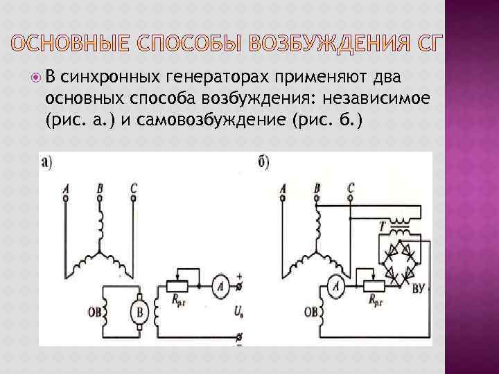 In synchronous generators, two main methods of excitation are used: independent (Fig. a.) and self-excitation (Fig. b.)
 With independent excitation, the excitation winding is powered by a direct current generator with an independent excitation winding located on the rotor shaft of a synchronous generator and rotating with it (high power). During self-excitation, the excitation winding is powered by the synchronous generator itself through a rectifier (low and medium power).
 With the help of the prime mover, the rotor inductor rotates. The magnetic field is located on the rotor and rotates with it, so the speed of rotation of the rotor is equal to the speed of rotation of the magnetic field - hence the name synchronous machine.
 When the rotor rotates, the magnetic flux of the poles crosses the stator winding and induces an EMF in it according to the law of electromagnetic induction: E = 4.44*f*w*kw*F, where: f – frequency of alternating current, Hz; w – number of turns; kw – winding coefficient; F – magnetic flux. Frequency of induced EMF (voltage, current) of a synchronous generator: f =p *n/60, where: p – number of pole pairs; n – rotor rotation speed, rpm.
 Replacing in: E = 4, 44*(p*p/60)*w*kw*Ф and, determining that: 4, 44*(p/60)*w*kw – relates to the design of the machine and creates a design factor: C = 4. 44*(p/60)*w*kw. Then: E = CE*n*F. Thus, like any generator based on the law of electromagnetic induction, the induced EMF is proportional to the magnetic flux of the machine and the rotor speed.
 Synchronous machines are also used as an electric motor, especially in high-power installations (over 50 kW)
 To operate a synchronous machine in motor mode, the stator winding is connected to a three-phase network, and the rotor winding is connected to a direct current source. As a result of the interaction of the rotating magnetic field of the machine with the direct current of the field winding, a torque M arises, which carries it away at the speed of the magnetic field.
 To connect the generator to the network it is necessary: the same phase rotation in the network and the generator; equality of network voltage and generator EMF; equality of generator EMF frequencies and network voltage; turn on the generator at the moment when the EMF of the generator in each phase is directed opposite to the network voltage. Failure to comply with these conditions leads to the fact that when the generator is turned on, currents arise that can be large and damage the generator.
Electric drives with synchronous motors can be divided into three classes based on the conditions of load formation: electric drives with a constant or slowly changing load, electric drives with a pulsating load, electric drives with a sharply changing load. The main technical characteristics of synchronous electric drives, depending on the type of load encountered, are given in Table. 6.1.
As follows from the table. 6.1, in electric drives with pulsating and sharply variable loads, it is necessary to automatically control the excitation of a synchronous motor. Automatic excitation control systems ensure stable operation of a synchronous motor during load surges or when the supply network voltage decreases. In these cases, automatic excitation control systems increase the excitation current, thereby increasing the maximum torque of the synchronous motor. In addition, changing the excitation current of a synchronous motor allows you to regulate the reactive power of the stator circuit of the motor.
Table 6.1
|
Load Types |
Mechanisms |
Range capacities |
Automatic regulation of excitation current |
|
Unchangeable |
Fans Blowers Compressors |
Yuch-YOO kW |
Not required |
|
Pulsating |
Pumping machines Piston compressors |
Necessary |
|
|
Sharply variable |
Crushers Mills Rolling mills Shears Saws |
1004-10000 kW |
Necessary |
The possibility of regulating reactive power in the stator circuit of a synchronous motor by changing its excitation current is illustrated by the vector diagrams shown in Fig. 6.14.
Rice. 6.14. Vector diagrams of a synchronous motor at different field winding currents: a - excitation current is less than rated; b - excitation current is equal to the rated current; c - excitation current is greater than rated
Vector diagram fig. 6.14, A corresponds to the excitation winding current less than the rated one, while the stator current vector / lags behind the network voltage vector LJ X at the angle cf. Reactive power is active-inductive. With increasing excitation current (Fig. 6.14 , b) EMF E), induced in the stator windings increases and can reach a value at which the stator current / will be in phase with the voltage (/, that is, costp = 1. Reactive power is zero. If the field winding current is further increased, then the stator current vector / , will lead in phase the voltage vector 6/, (working with leading coscp) and the synchronous motor will be equivalent to an active-capacitive load connected in parallel with the network (Fig. 6.14, V).
In Fig. 6.15 shows ^/-shaped characteristics. They show the dependence of the stator current / of a synchronous motor on the excitation current / in at various loads on the motor shaft (M s! With numerical values of the parameters, 67-shaped characteristics allow you to correctly select the excitation current in order to ensure the required operating mode of the synchronous motor.
Currently, automatic excitation control systems are used in practice. Depending on the circuit design, automatic excitation current control systems can perform the following main functions:
- ensure stable operation of a synchronous motor under given load conditions;
- maintain optimal voltage in the load node to which the synchronous motor is connected;
- ensure a minimum of energy losses in the synchronous motor and power supply system.

Rice. 6.15.
When choosing automatic control circuits for the excitation current, they are guided by the following provisions:
- in electric drives with a constant load and slight fluctuations in the supply voltage, the installation of devices for automatic control of the excitation current, as a rule, is not provided;
- In electric drives with a pulsating load or shock load, it is necessary to install devices for automatic control of the excitation current. The excitation current of such motors is regulated as a function of the active stator current, which makes it possible to significantly increase the overload capacity of the motor, and in some cases reduce its installed power;
- when operating a synchronous motor with a sharply variable load, it is also necessary to install devices for automatic regulation of the excitation current, however, in this case, the control system must respond not only to changes in the load, but also to the speed of this change.
The simplest diagram of an automatic control system for excitation current for electric drives with a pulsating load is shown in Fig. 6.16. The system makes it possible to provide excitation of a synchronous motor in all normal operating modes. When the load on the motor shaft changes, the stator winding current / increases, which
leads to an increase in the positive current feedback signal Uoc[
and, as a consequence, to an increase in the voltage of the controlled rectifier and an increase in the excitation current of the synchronous motor.

Rice. 6.16.
Taking into account the proportionality between the EMF and the magnetic flux Ф, and therefore the field winding current / in, equation (1.71) can be written as follows:
Where to to - proportionality coefficient between flux Ф and excitation current 1 a.
Analysis (6.10) shows that an increase in the excitation current causes an increase in the maximum torque of a synchronous motor. Consequently, automatic excitation control leads to increased dynamic stability of a synchronous motor when the load on its shaft changes and damping of rotor swing.
It is also possible to maintain the optimal voltage in the load node to which the synchronous motor is connected using automatic excitation current control systems.
To improve the performance of an extensive industrial network, reactive power is compensated by installing synchronous motors or synchronous compensators. In Fig. Figure 6.17 shows a diagram of a load node to which consumers generating and consuming reactive power are connected.

Rice. 6.1 7.
Inductive reactive current / p is equal to the sum of reactive currents P
consumers (transformers; asynchronous motors; DC motors powered by adjustable converters) and is determined by the expression
Where / . - reactive current of the /th load.
To fully compensate for reactive power in the network, the following condition must be met:
Reactive current of a synchronous machine required to compensate for the network voltage drop:
Where X p- equivalent phase reactance of the network taking into account all consumers: 
AU C- network voltage drop;  - phase voltage of the network;
 - total phase resistance of all consumers of electrical energy, except for the synchronous motor; p, is the electrical conductivity of the circuit section; U, t - line voltage; S K With -
network short circuit power.
Modern systems for automatic control of the excitation current of synchronous motors, designed to compensate for reactive power, are built on the principle of subordinate control of coordinates and provide for the regulation of three variables: excitation current, voltage drop across the equivalent phase reactance of the network, reactive current of the synchronous motor stator. The functional diagram of such a system is shown in Fig. 6.18.

Rice. 6.18.
The internal circuit provides regulation of the excitation current using the excitation current regulator PTB. The command for the excitation current of a synchronous motor is the output signal U pj regulator
reactive current PRT. The feedback voltage for the excitation current of the synchronous motor is subtracted from this signal. The output signal?/PTB of the excitation current regulator affects the controlled
UV rectifier, changing the excitation current / in a synchronous motor.
The reactive current regulator is included in the second circuit - the reactive current control circuit I. The signals are summed at its input
negative feedback on reactive current (7 ort and the reactive current reference signal - from the output of the PH voltage regulator.
At the input of the PH voltage regulator, negative voltage feedback signals are summed U on. Voltage feedback is formed from reactive current and equivalent phase resistance of the network: U0H = I X C1. The voltage regulator is adaptive, proportional type, changing the gain when the supply voltage drops below (0.8 - 0.85) U H .
The transfer functions of control loops and current regulators are obtained under the following basic assumptions:
The saturation of the magnetic circuit of a synchronous motor is not taken into account;
Controlled rectifier - first order aperiodic link with transfer function
Where k.sh- gain of the controlled rectifier (thyristor converter);  - delay time constant
thyristor converter; t in- number of voltage pulsations of the thyristor converter during the period of supply voltage; co e -
the angular frequency of the supply network is equal to 314.15 s" 1, at a supply network frequency / s = 50 Hz; all filter time constants and small inertia are summed up and replaced by one time constant.
Transfer functions of regulators in accordance with the modular optimum:
Excitation current regulator

Reactive current regulator

Where T- time constant of the excitation current control circuit; 7j ipp - time constant of the reactive current control loop; to Japanese- transmission coefficient of the excitation current sensor; R B - active resistance of the excitation winding of a synchronous motor; to Yarya- transmission coefficient of the reactive current sensor; to xia- transmission coefficient of a synchronous motor controlled via the excitation winding circuit by changing the voltage.
Compensation of the forcing link 7^ rtv R+1 in the numerator of the transfer function of the excitation current regulator WpTB(p) is performed inside the control object - a synchronous motor. Thus, in the reactive current control loop there is no time constant that needs to be compensated, therefore, implementing a controller with a proportional-integral characteristic makes it possible to eliminate the disadvantage of the subordinate control system.
The use of a synchronous motor with automatic excitation control makes it possible to maintain reactive power and voltage in the load node at a given level. The task in the automatic excitation regulator to generate reactive power is a variable value that depends on the parameters and load of the supply network.
Synchronous machines are devices with a rotor speed in which it is always equal to or a multiple of a similar indicator of the magnetic field inside the air gap, which is created by the current passing through the armature winding. The operation of this type of machine is based on the principle of electromagnetic induction.
Excitation of synchronous machines
Synchronous machines can be excited by electromagnetic action or a permanent magnet. In the case of electromagnetic excitation, a special direct current generator is used, which powers the winding; due to its main function, this device is called an exciter. It is worth noting that the excitation system is also divided into two types according to the method of influence - direct and indirect. The direct excitation method implies that the shaft of the synchronous machine is directly mechanically connected to the exciter rotor. The indirect method assumes that in order to make the rotor rotate, another motor is used, for example an asynchronous electric machine.
The most widely used method today is the direct method of excitation. However, in cases where the excitation system is supposed to operate with powerful synchronous electric machines, independent excitation generators are used, the windings of which are supplied with current from another direct current source, called a subexciter. Despite its bulkiness, this system allows for greater stability in operation, as well as finer-tuning of characteristics.
The device of a synchronous machine
A synchronous electric machine has two main components: an inductor (rotor) and an armature (stator). The most optimal and therefore widespread today is the scheme when the armature is placed on the stator, while the inductor is located on the rotor. A prerequisite for the functioning of the mechanism is the presence of an air gap between these two parts. The armature in this case is a stationary part of the device (stator). It can consist of either one or several windings, depending on the required power of the magnetic field that it must create. The stator core is usually made from individual thin sheets of electrical steel.
.jpg)

The inductor in synchronous electric machines is an electromagnet, with the ends of its winding leading directly to the slip rings on the shaft. During operation, the inductor is excited by direct current, due to which the rotor creates an electromagnetic field that interacts with the magnetic field of the armature. Thus, thanks to the direct current exciting the inductor, a constant frequency of rotation of the magnetic field inside the synchronous machine is achieved.
Operating principle of synchronous machines
The operating principle of a synchronous machine is based on the interaction of two types of magnetic fields. One of these fields is formed by the armature, while the other arises around an electromagnet excited by direct current - an inductor. Immediately after reaching operating power, the magnetic field created by the stator and rotating inside the air gap meshes with the magnetic fields at the poles of the inductor. Thus, in order for a synchronous machine to reach its operating speed, a certain amount of time is required to accelerate it. After the machine accelerates to the required frequency, power is supplied to the inductor from a DC source.

When considering the principle of operation of a synchronous generator, it was found that an MMF source (inductor) is located on the rotor of the synchronous generator, creating a magnetic field in the generator. With the help of a drive motor (PD), the generator rotor is driven into rotation at a synchronous frequency n 1 . In this case, the magnetic field of the rotor also rotates and, engaging with the stator winding, induces an EMF in it.
Synchronous motors are structurally almost no different from synchronous generators. They also consist of a stator with a winding and a rotor. Therefore, regardless of the operating mode, any synchronous machine needs an excitation process - the induction of a magnetic field in it.
The main method of exciting synchronous machines is electromagnetic excitation, the essence of which is that an excitation winding is placed at the rotor poles. When a direct current passes through this winding, an excitation MMF arises, which induces a magnetic field in the magnetic system of the machine.
Until recently, special independent excitation direct current generators, called exciters B, were used to power the excitation winding (Fig. 1.1, a) , the excitation winding of which (OB) received DC power from another generator (parallel excitation), called a subexciter (SU). The rotor of a synchronous machine and the armatures of the exciter and subexciter are located on a common shaft and rotate simultaneously. In this case, the current enters the excitation winding of the synchronous machine through slip rings and brushes. To regulate the excitation current, control rheostats are used, connected in the exciter excitation circuit (r 1) and subexciter (r 2).
In synchronous generators of medium and high power, the process of regulating the excitation current is automated.
In high-power synchronous generators - turbogenerators - sometimes inductor-type alternating current generators are used as exciters (see § 23.6). At the output of such a generator, a semiconductor rectifier is switched on.
Rice. 1.1.
In this case, the excitation current of the synchronous generator is adjusted by changing the excitation of the inductor generator.
A contactless electromagnetic excitation system has been used in synchronous generators, in which the synchronous generator does not have slip rings on the rotor.
In this case, an alternating current generator is used as an exciter (Fig. 1.1, 5), in which winding 2, in which the EMF is induced (armature winding), is located on the rotor, and excitation winding 1 is located on the stator. As a result, the exciter armature winding and the excitation winding of the synchronous machine turn out to be rotating, and their electrical connection is carried out directly, without slip rings and brushes. But since the exciter is an alternating current generator, and the excitation winding must be powered with direct current, at the output of the exciter armature winding a semiconductor converter 3 is turned on, mounted on the shaft of the synchronous machine and rotating together with the excitation winding of the synchronous machine and the exciter armature winding. DC power supply of excitation winding 1 of the exciter is provided from the subexciter (SU) - a direct current generator.
The absence of sliding contacts in the excitation circuit of a synchronous machine makes it possible to increase its operational reliability and increase efficiency.
In synchronous generators, including hydrogenerators (see § 1.2), the principle of self-excitation has become widespread (Fig. 1.2, a), when the alternating current energy required for excitation is taken from the stator winding of the synchronous generator and through a step-down transformer and a rectifying semiconductor converter (PP) is converted into direct current energy. The principle of self-excitation is based on the fact that the initial excitation of the generator occurs due to the residual magnetism of the machine's magnetic circuit.

Rice. 1.2.
In Fig. 1.2, b shows a block diagram of an automatic self-excitation system of a synchronous generator (SG) with a rectifier transformer (VT) and a thyristor converter (TC), through which alternating current electricity from the stator circuit of the SG, after conversion to direct current, is supplied to the excitation winding. The thyristor converter is controlled by means of an automatic AVR stimulation regulator, the input of which receives voltage signals at the output of the SG (through the voltage transformer TN) and the load current of the SG (from the current transformer CT). The circuit contains a protection unit BZ, which provides protection for the excitation winding and thyristor converter TP from overvoltage and current overload.
In modern synchronous motors, thyristor exciting devices are used for excitation; they are connected to the alternating current network and automatically control the excitation current in all possible operating modes of the motor, including transient ones. This method of excitation is the most reliable and economical, since the efficiency of thyristor exciter devices is higher than that of direct current generators. The industry produces thyristor exciter devices for various excitation voltages with a permissible direct current value of 320 A.
The most widely used in modern series of synchronous motors are exciter thyristor devices of the types TE8-320/48 (excitation voltage 48 V) and TE8-320/75 (excitation voltage 75 V). The power spent on excitation usually ranges from 0.2 to 5% of the net power of the machine (a lower value applies to high-power machines).
In low-power synchronous machines, the principle of excitation by permanent magnets is used, when permanent magnets are located on the rotor of the machine. This method of excitation makes it possible to rid the machine of the excitation winding. As a result, the machine design is simplified, more economical and reliable. However, due to the scarcity of materials for the manufacture of permanent magnets with a large supply of magnetic energy and the complexity of their processing, the use of excitation by permanent magnets is limited to machines with a power of no more than a few kilowatts.


