
Let's take for example a standard electronic transformer labeled 12V 50W, which is used to power a table lamp. The schematic diagram will be like this:

The electronic transformer circuit works as follows. The mains voltage is rectified using a rectifier bridge to a half-sinusoidal voltage with double the frequency. Element D6 of type DB3 in the documentation is called “TRIGGER DIODE”, - this is a bidirectional dinistor in which the polarity of the inclusion does not matter and it is used here to start the transformer converter. The dinistor is triggered during each cycle, starting the generation of a half-bridge. The opening of the dinistor can be adjusted. This can be done use for example for the function of a connected lamp.The generation frequency depends on the size and magnetic conductivity of the feedback transformer core and the parameters of the transistors, usually in the range of 30-50 kHz.

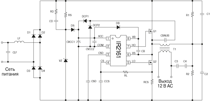
Currently, the production of more advanced transformers with the IR2161 chip has begun, which provides both simplicity of design of the electronic transformer and a reduction in the number of components used, as well as high performance. The use of this microcircuit significantly increases the manufacturability and reliability of the electronic transformer for powering halogen lamps. The schematic diagram is shown in the figure.
Features of the electronic transformer on IR2161:
Intelligent half bridge driver;
Load short circuit protection with automatic restart;
Overcurrent protection with automatic restart;
Swing the operating frequency to reduce electromagnetic interference;
Micropower start-up 150 µA;
Possibility of use with phase dimmers with control by leading and trailing edges;
Compensation for output voltage offset increases lamp life;
Soft start, eliminating current overload of lamps.

Input resistor R1 (0.25 watt) is a kind of fuse. Transistors of type MJE13003 are pressed to the body through an insulating gasket with a metal plate. Even when operating at full load, the transistors heat up slightly. After the mains voltage rectifier, there is no capacitor to smooth out the ripples, so the output voltage of the electronic transformer when operating on a load is a 40 kHz rectangular oscillation, modulated by 50 Hz mains voltage ripples. Transformer T1 (feedback transformer) - on a ferrite ring, the windings connected to the bases of the transistors contain a couple of turns, the winding connected to the connection point of the emitter and collector of the power transistors - one turn of single-core insulated wire. Transistors MJE13003, MJE13005, MJE13007 are usually used in ET. Output transformer on a ferrite W-shaped core.

To use an electronic transformer in a pulse mode, you need to connect a rectifier bridge on high-frequency diodes to the output (regular KD202, D245 will not work) and a capacitor to smooth out ripples. At the output of the electronic transformer, a diode bridge is installed using KD213, KD212 or KD2999 diodes. In short, we need diodes with a low voltage drop in the forward direction, capable of operating well at frequencies of the order of tens of kilohertz.

The electronic transformer converter does not work normally without a load, so it must be used where the load is constant in current and consumes sufficient current to reliably start the ET converter. When operating the circuit, it must be taken into account that electronic transformers are sources of electromagnetic interference, therefore an LC filter must be installed to prevent interference from penetrating the network and the load.

Personally, I used an electronic transformer to make a switching power supply for a tube amplifier. It also seems possible to power them with powerful Class A ULFs or LED strips, which are specifically designed for sources with a voltage of 12V and a high output current. Naturally, such a tape is connected not directly, but through a current-limiting resistor or by correcting the output power of an electronic transformer.
Discuss the article ELECTRONIC TRANSFORMER DIAGRAM FOR HALOGEN LAMPS
The device has a fairly simple circuit. A simple push-pull self-oscillator, which is made using a half-bridge circuit, the operating frequency is about 30 kHz, but this indicator strongly depends on the output load.
The circuit of such a power supply is very unstable, it does not have any protection against short circuits at the output of the transformer, perhaps precisely because of this, the circuit has not yet found widespread use in amateur radio circles. Although recently there has been a promotion of this topic on various forums. People offer various options for modifying such transformers. Today I will try to combine all these improvements in one article and offer options not only for improvements, but also for strengthening the ET.
We won’t go into the basics of how the circuit works, but let’s get down to business right away.
We will try to refine and increase the power of the Chinese Taschibra electric vehicle by 105 watts.
To begin with, I want to explain why I decided to take on the powering and alteration of such transformers. The fact is that recently a neighbor asked me to make him a custom-made charger for a car battery that would be compact and lightweight. I didn’t want to assemble it, but later I came across interesting articles that discussed remaking an electronic transformer. This gave me the idea - why not try it?
Thus, several ETs from 50 to 150 Watts were purchased, but experiments with conversion were not always completed successfully; of all, only the 105 Watt ET survived. The disadvantage of such a block is that its transformer is not ring-shaped, and therefore it is inconvenient to unwind or rewind the turns. But there was no other choice and this particular block had to be remade.
As we know, these units do not turn on without load; this is not always an advantage. I plan to get a reliable device that can be freely used for any purpose without fear that the power supply may burn out or fail during a short circuit.
Improvement No. 1
The essence of the idea is to add short-circuit protection and also eliminate the above-mentioned drawback (activation of a circuit without an output load or with a low-power load).

Looking at the unit itself, we can see the simplest UPS circuit; I would say that the circuit has not been fully developed by the manufacturer. As we know, if you short-circuit the secondary winding of a transformer, the circuit will fail in less than a second. The current in the circuit increases sharply, the switches instantly fail, and sometimes even the basic limiters. Thus, repairing the circuit will cost more than the cost (the price of such an ET is about $2.5).

The feedback transformer consists of three separate windings. Two of these windings power the base switch circuits.
First, remove the communication winding on the OS transformer and install a jumper. This winding is connected in series with the primary winding of the pulse transformer.
Then we wind only 2 turns on the power transformer and one turn on the ring (OS transformer). For winding, you can use a wire with a diameter of 0.4-0.8 mm.


Next, you need to select a resistor for the OS, in my case it is 6.2 ohms, but a resistor can be selected with a resistance of 3-12 ohms, the higher the resistance of this resistor, the lower the short-circuit protection current. In my case, the resistor is a wirewound one, which I do not recommend doing. We select the power of this resistor to be 3-5 watts (you can use from 1 to 10 watts).

During a short circuit on the output winding of a pulse transformer, the current in the secondary winding drops (in standard ET circuits, during a short circuit, the current increases, disabling the switches). This leads to a decrease in the current on the OS winding. Thus, generation stops and the keys themselves are locked.
The only drawback of this solution is that in the event of a long-term short circuit at the output, the circuit fails because the switches heat up quite strongly. Do not expose the output winding to a short circuit lasting more than 5-8 seconds.
The circuit will now start without load; in a word, we have a full-fledged UPS with short-circuit protection.

Improvement No. 2
Now we will try to smooth out the mains voltage from the rectifier to some extent. For this we will use chokes and a smoothing capacitor. In my case, a ready-made inductor with two independent windings was used. This inductor was removed from the UPS of the DVD player, although homemade inductors can also be used.

After the bridge, an electrolyte with a capacity of 200 μF should be connected with a voltage of at least 400 Volts. The capacitor capacity is selected based on the power of the power supply 1 μF per 1 watt of power. But as you remember, our power supply is designed for 105 Watts, why is the capacitor used at 200 μF? You will understand this very soon.
Improvement No. 3
Now about the main thing - increasing the power of the electronic transformer and is it real? In fact, there is only one reliable way to power it up without much modification.
For powering up, it is convenient to use an ET with a ring transformer, since it will be necessary to rewind the secondary winding; it is for this reason that we will replace our transformer.
The network winding is stretched across the entire ring and contains 90 turns of wire 0.5-0.65 mm. The winding is wound on two folded ferrite rings, which were removed from an ET with a power of 150 watts. The secondary winding is wound based on needs, in our case it is designed for 12 Volts.
It is planned to increase the power to 200 watts. That is why an electrolyte with a reserve, which was mentioned above, was needed.
We replace the half-bridge capacitors with 0.5 μF; in the standard circuit they have a capacity of 0.22 μF. Bipolar keys MJE13007 are replaced with MJE13009.
The power winding of the transformer contains 8 turns, the winding was done with 5 strands of 0.7 mm wire, so we have a wire in the primary with a total cross-section of 3.5 mm.
Go ahead. Before and after the chokes we place film capacitors with a capacity of 0.22-0.47 μF with a voltage of at least 400 Volts (I used exactly those capacitors that were on the ET board and which had to be replaced to increase the power).

Next, replace the diode rectifier. In standard circuits, conventional rectifier diodes of the 1N4007 series are used. The current of the diodes is 1 Ampere, our circuit consumes a lot of current, so the diodes should be replaced with more powerful ones in order to avoid unpleasant results after the first turn on of the circuit. You can use literally any rectifier diodes with a current of 1.5-2 Amps, a reverse voltage of at least 400 Volts.
All components except the generator board are mounted on a breadboard. The keys were secured to the heat sink through insulating gaskets.
We continue our modification of the electronic transformer, adding a rectifier and filter to the circuit.
The chokes are wound on rings made of powdered iron (removed from a computer power supply unit) and consist of 5-8 turns. It is convenient to wind it using 5 strands of wire with a diameter of 0.4-0.6 mm each.

We select a smoothing capacitor with a voltage of 25-35 Volts; one powerful Schottky diode (diode assemblies from a computer power supply) is used as a rectifier. You can use any fast diodes with a current of 15-20 Amps.

Halogen lamps are increasingly used every day in decorating various shopping malls and shop windows. The bright colors and richness of the image rendering make them increasingly popular. Their service life is much longer than that of conventional lamps. At the same time, they can work for a long time without switching off. Halogen lamps use filaments, but the glow process is different in comparison with incandescent lamps due to the filling of the cylinder with a special composition. Such light bulbs are used in various lamps, chandeliers, kitchen furniture and come in 220 and 12 volt. A power supply for halogen lamps with a voltage of 12 volts is necessary, because if they are connected directly to the electrical network, a short circuit will occur.

Specifications
The voltage of halogen lamps is not only 220 and 12 volts. On sale you can find 24 and even 6 volt light bulbs. The power can also be different - 5, 10, 20 watts. Halogen lamps from 220 V are connected directly to the network. Those that operate on 12 V require special devices that convert current from the network to 12 volts - so-called transformers or special power supplies.
Twelve volt halogens work very well. Previously, in the 90s, a large 50 Hz transformer was used, which ensured the operation of only one halogen lamp. Modern lighting uses pulsed high-frequency converters. They are very small in size, but can pull 2 - 3 lamps at the same time.
On the modern market there are both expensive and cheap power supplies. As a percentage of expensive ones, about 5% are sold, and much more cheap ones. Although, in principle, high cost is not a guarantee of reliability. Cool converters, unfortunately, do not use high-quality parts, but only use clever circuit “bells and whistles” that contribute to the normal operation of the power supply, at least during the warranty period. As soon as it runs out, the device burns out.
Classification
Transformers are electromagnetic and electronic (pulse). Electromagnetic ones are affordable, reliable, and can be made with your own hands if desired. They also have their disadvantages - decent weight, large overall dimensions, increased temperature during prolonged operation. And voltage drops significantly shorten the life of halogen lamps.

Electronic transformers weigh much less, they have a stable output voltage, they do not heat up much, they can have short-circuit protection and soft start, which increases the life of the lamp.
![]()
Transformers for halogen lamps
The analysis will be carried out using the example of a power supply from Feron German Technology. The output of this transformer is no less than 5 amperes. For such a small box the value is amazing. The case is made in a hermetically sealed manner, with the absence of any kind of ventilation. This is probably why some copies of such power supplies melt from high temperatures.

The converter circuit in the first version is very simple. The set of all the details is so minimal that it is unlikely that anything can be thrown out of it. When enumerating we see:
- diode bridge;
- RC circuit with a dinistor to start the generator;
- generator assembled on a half-bridge circuit;
- transformer that reduces the input voltage;
- low resistance resistor that serves as a fuse.
With a large voltage drop, such a converter will “die” 100%, taking the entire “blow” upon itself. Everything is made from a fairly cheap set of parts. Only there are no complaints about the transformers, because they are made to last.

The second option looks very weak and unfinished. Resistors R5 and R6 are inserted into the emitter circuits to limit the current. At the same time, the blocking of transistors in the event of a sharp increase in current is not thought out at all (it simply does not exist!). The electrical circuit (in the diagram it is red in the diagram) raises doubts.

The Feron German Technology company produces halogen lamps with a power of up to 60 watts. The output current of the power supply is 5 amperes. This is a bit much for such a light bulb.

When removing the cover, pay special attention to the dimensions of the radiator. For a 5 amp output they are very small.
Calculation of transformer power for lamps and connection diagram
Various transformers are sold today, so there are certain rules for selecting the required power. You should not take a transformer that is too powerful. It will work practically idle. Lack of power will lead to overheating and further failure of the device.
You can calculate the power of the transformer yourself. The problem is rather mathematical and is within the capabilities of every novice electrician. For example, it is necessary to install 8 halogen spot lights with a voltage of 12 V and a power of 20 watts. The total power will be 160 watts. We take approximately a 10% margin and purchase a power of 200 watts.
Scheme No. 1 looks something like this: there is a single-key switch on line 220, with the orange and blue wires connected to the transformer input (primary terminals).

On the 12 volt line, all lamps are connected to a transformer (to the secondary terminals). The connecting copper wires must have the same cross-section, otherwise the brightness of the light bulbs will be different.
Another condition: the wire connecting the transformer to the halogen lamps must be at least 1.5 meters long, preferably 3. If you make it too short, it will start to heat up and the brightness of the lamps will decrease.

Scheme No. 2 – for connecting halogen lamps. Here you can do things differently. Break, for example, six lamps into two parts. For each, install a step-down transformer. The correctness of this choice is due to the fact that if one of the power supplies breaks down, the second part of the lamps will still continue to work. The power of one group is 105 watts. With a small safety factor, we find that you need to purchase two 150-watt transformers.
Advice! Power each step-down transformer with its own wires and connect them in a junction box. Leave the connection points freely accessible.
Do-it-yourself power supply modification
To operate halogen lamps, pulsed current sources with high-frequency voltage conversion began to be used. During home production and setup, expensive transistors quite often burn out. Since the supply voltage in the primary circuits reaches 300 volts, very high requirements are placed on insulation. All these difficulties can be completely avoided by using a ready-made electronic transformer. It is used to power 12-volt halogen backlights (in stores), which are powered from a standard electrical outlet.
There is a certain opinion that getting a homemade switching power supply is a simple matter. You can only add a rectifier bridge, a smoothing capacitor and a voltage stabilizer. In reality, everything is much more complicated. If you connect an LED to the rectifier, then only one ignition can be detected when turned on. If you turn the converter off and on again, another flash will occur. In order for a constant glow to appear, it is necessary to connect an additional load to the rectifier, which, taking away useful power, would convert it into heat.
One of the options for self-manufacturing a switching power supply
The described power supply can be made from an electronic transformer with a power of 105 W. In practice, this transformer resembles a compact pulse voltage converter. For assembly, you will additionally need a matching transformer T1, a mains filter, a rectifier bridge VD1-VD4, and an output choke L2.
 Bipolar power supply circuit
 Such a device operates stably for a long time with a low-frequency amplifier with a power of 2x20 watts. At 220 V and a current of 0.1 A, the output voltage will be 25 V; when the current increases to 2 amperes, the voltage drops to 20 volts, which is considered normal operation.
The current, bypassing the switch and fuses FU1 and FU2, goes to a filter that protects the circuit from interference from the pulse converter. The middle of capacitors C1 and C2 is connected to the shielding casing of the power supply. Then the current is supplied to input U1, from where a reduced voltage is supplied from the output terminals to the matching transformer T1. The alternating voltage from the other (secondary winding) rectifies the diode bridge and smoothes the L2C4C5 filter.
Self-assembly
Transformer T1 is manufactured independently. The number of turns on the secondary winding affects the output voltage. The transformer itself is made on a K30x18x7 ring magnetic core made of M2000NM ferrite. The primary winding consists of a PEV-2 wire with a diameter of 0.8 mm, folded in half. The secondary winding consists of 22 turns of PEV-2 wire, folded in half. By connecting the end of the first half-winding to the beginning of the second, we obtain the midpoint of the secondary winding. We also make the throttle ourselves. It is wound on the same ferrite ring, both windings contain 20 turns.
Rectifier diodes are located on a radiator with an area of at least 50 sq.cm. Please note that diodes whose anodes are connected to the negative output are insulated from the heat sink with mica spacers.
Smoothing capacitors C4 and C5 consist of three K50-46 connected in parallel with a capacity of 2200 μF each. This method is used to reduce the overall inductance of electrolytic capacitors.
It would be better to install a surge filter at the input of the power supply, but it is possible to work without it. For a line filter choke, you can use a DF of 50 Hz.
All parts of the power supply are mounted on a board made of insulating material. The resulting structure is placed in a shielding casing made of thin sheet brass or tinned sheet. Don't forget to drill holes in it for air ventilation.
A correctly assembled power supply does not require adjustment and starts working immediately. But just in case, you can check its performance by connecting a resistor with a resistance of 240 Ohms and a dissipation power of 3 W to the output.
Step-down transformers for halogen lamps generate a very large amount of heat during operation. Therefore, several requirements must be met:
- Do not connect the power supply without load.
- Place the unit on a non-flammable surface.
- The distance from the block to the light bulb is at least 20 centimeters.
- For better ventilation, install the transformer in a niche with a volume of at least 15 liters.
A power supply is required for halogen lamps operating on 12 volts. It is a kind of transformer that lowers the input 220 V to the required values.
A halogen lamp is one of the varieties of incandescent lamps, with the only difference from a simple light bulb being that pairs of bromine and iodine halogens are pumped into the latter’s cylinder. This type of light bulbs is produced both for direct connection to a 220 V electrical network, and low-voltage ones, which are switched on through a step-down transformer.
When using low-voltage halogen lamps with an operating voltage of 12 V, to turn them on, you must use a step-down transformer, whose primary voltage is equal to the mains voltage (220/127 V), and the secondary voltage is equal to the operating voltage of the light bulb.
Transformers are available with output voltage: 6/12/24 V, they are:
- Winding (electromagnetic) - which are based on the principle of operation of a magnetic field between the electric windings of a transformer;
- Electronic – work is based on the use of electronic devices.
Advantages of electromagnetic devices:
- Reliability;
- Ability to withstand power surges.
Disadvantages of electromagnetic devices:
- Significant weight and overall dimensions;
- Increased noise level during operation;
- When voltage surges occur in the supply network, the voltage surges are directly proportional to the secondary voltage, which leads to pulsation of the luminous flux of light sources.
Electronic transformers for halogen lamps have a number of advantages over winding ones, namely:
- Smaller overall dimensions and weight of the device;
- High efficiency, which is 95 - 99%, while winding ones are 75 - 80%;
- Most protected from short circuit currents;
- During operation they create less noise;
- Idle mode is more stable;
- Thanks to overload protection, temperature control and soft start of halogen lamps, they can increase the life of the latter.
Electronic transformer circuit for 12 V halogen lamps
Electronic transformer for halogen lamps circuit diagramThe simplest version of an electronic device, which is widely used in practice, is a device with a half-bridge connection circuit and positive current feedback (the diagram is shown below).
The operation of a transformer assembled according to this scheme is carried out as follows:
- When voltage is applied to the input of the device, capacitors C3 and C4 are charged;
- In the section “R5 – C2 – VS1” a pulse is generated that serves to start the halogen lamp;
- A charge occurs on capacitor C2 and when a voltage sufficient for the opening threshold of the dinistor is reached, the latter opens, after which the voltage is supplied to the base of transistor VT2;
- Transistor VT2 opens and electric current is supplied to the device circuit (section: capacitors C3 and C4 - primary winding T2 - winding III - transistor VT2 - diode bridge VD1);
- A voltage appears on winding II, which keeps transistor VT2 open;
- At the same time, reverse voltage is supplied to transistor VT1 from winding I (the transformer windings are turned on in antiphase);
- The current passing through winding III leads to saturation of the transformer, after which the voltage on windings I and II decreases to zero values;
- Transistor VT2 closes, transformer T1 comes out of saturation;
- The voltage increases on windings I and II;
- Transistor VT1 opens, electric current is supplied to the device circuit (section: diode bridge VD1 - winding III - primary winding of transformer T2 - capacitors C3 and C4);
- The process is repeated, and a second half-wave of voltage is formed in the consumer line (load).
The presence of diode VD4 in the circuit makes it possible to maintain capacitor C2 in a discharged state.
After the completion of the half-cycle of the rectified network voltage, the generation process stops. At the beginning of the next half-cycle, generation starts again.
The advantage of an electronic transformer for powering halogen lamps is that this electronic device will not start if there is no load (halogen lamps).
There are a large number of different electronic transformer circuits for powering halogen lamps, which differ in the power of the connected lamps, output voltage, configuration and additional improvements and protections.
Selecting a transformer for halogen lamps
When choosing a transformer to power halogen lamps, the following device parameters should be taken into account:
- Rated power;
- Output voltage.
The wattage rating determines the number of light bulbs (luminaires) that can be connected to a given electronic device.
An important factor when choosing a transformer is its geometric dimensions, since depending on the design and design, models can vary greatly.The cost of the devices is also an important factor when choosing this equipment. The higher the power rating, the higher the cost. The cost is also affected by the country and manufacturer.
Such electronic devices are produced by foreign and domestic enterprises. The most widely used devices in our country are the following companies: Osram, VS, Comtech, Tashibra and Delux.
Transformer power calculation
To determine the power of the required transformer, it is necessary to determine:
- Power of one lamp (lamp);
- Number of lamps (luminaires);
- Connection diagram for lamps.
The calculation must begin with the development of a power supply diagram for a specific room. To do this, draw a plan indicating the number and power of lamps. The power is summed up and the resulting value is multiplied by K = 1.1 (safety factor), which avoids overloading the selected device. The resulting value is the value that should be used when choosing a device.
With a large number of lamps, as well as to create reliability of the lighting system, lamps can be divided into groups. With this design of the lighting system, the power of each individual transformer is reduced.
Transformers for halogen lamps are available in power: 60/70/105/150/210/250/400 W.
Connecting the device to the power supply circuit for halogen lamps
Each factory-produced electronic device indicates its technical characteristics, graphic designation and type of lamps for which the device is used.
The transformer has terminals at the “input” and “output” of the device, with the neutral and phase wires marked.
Basic connection requirements:
- Halogen lamps are connected in parallel to the transformer output;
- The distance from the transformer to the load should not exceed 3 meters;
- It must be taken into account that during operation the transformer heats up, which can negatively affect other equipment mounted nearby.
Connecting light sources (lamps) can be done in the following ways:
Installation Requirements
- The surface on which the device is mounted must be resistant to heat and not flammable.
- The distance from the device to the nearest light bulb must be at least 20 cm;
- The niche (installation unit) must have a volume of at least 10.0 liters, which will ensure the required ventilation of the device.
How to check serviceability
Since an electronic transformer consists of a certain set of electronic components, the operation of the device as a whole, in the absence of combustion of the connected light sources and the serviceability of the supply circuit, can be checked by anyone with basic knowledge in the field of electronics.
To check the functionality, you will need a multimeter with the functions of checking direct and alternating voltage, resistance and having a “continuity” mode of the electrical circuit.
For a more accurate check of electronic components, it is recommended to unsolder them from the circuit board. Checked:
- Diodes.
Multimeter in dialing mode. The red probe is on the positive, the black probe is on the minus - when the diode is working properly, a characteristic sound is produced. When the probes are applied in the opposite direction, nothing should happen, otherwise a breakdown of the diode has occurred.
- Transistors.
To check, it is necessary to “ring” the base-emitter and base-collector transitions to check their permeability in one direction and the other.
- Transformer winding.
The integrity of the windings and the absence of interturn short circuits are checked.
- Capacitors.
To check, use a multimeter to set the resistance to 2000 kOhm. The positive probe of the device is applied to the minus of the capacitor, the negative to the plus. The display of the device should show numbers that increase almost to the set measurement limit (2000 kOhm). Then the number “1” should appear, indicating infinite resistance. This indicates the health of the capacitor and its ability to accumulate charge.


When selecting equipment for LED backlighting or LED lighting, the task of choosing a power supply for the system inevitably arises. LED equipment specialists always suggest using specialized power supplies. A person who encounters this equipment for the first time, as a rule, has a completely natural question - why can’t an electronic transformer be used for halogen lamps? It, with the same power, has a smaller size, a lower price, and its output voltage is also 12 volts. Those who just want to get an answer to this question without going into details can jump straight to the conclusions at the end of the article.
For those who want to understand the issue in more detail, a little theory.
To begin with, I would like to note that almost all modern power supplies are pulse converters. Their fundamental difference from previously used analog (or linear) power supplies is that the voltage conversion in them is carried out not at the frequency of the mains supply (50 Hz), but at a much higher frequency (usually in the range of 30000-50000 Hz). Thanks to the transition to such frequencies, it was possible to significantly reduce the size and weight of power supplies, as well as significantly increase their efficiency, which in modern models reaches 95%.
To understand the difference between a full-fledged power supply and an electronic transformer, let's look at their internal structure.
Let's consider the block diagram of a conventional electronic transformer for powering halogen lamps (Fig. 1).
Fig. 1 Block diagram of an electronic transformer designed to power halogen lamps.
Alternating current with a frequency of 50 Hz and a voltage of 220 V (Fig. 2a) is supplied to the input rectifier, which is usually a diode bridge. At the output of the rectifier (Fig. 2b), we receive voltage pulses of the same polarity and double frequency - 100 Hz.


Fig.2 Voltage waveforms at the input (a) and output (b) of the rectifier.
Next, this voltage is supplied to a cascade made of key transistors, which are put into generation mode using positive feedback. Thus, high-frequency pulses with the generation frequency and amplitude of the mains voltage are formed at the output of this cascade. It is very important for our case to pay attention to the fact that generation in such a circuit does not always occur, but only under the condition that the load of the electronic transformer is within certain limits, for example, from 30 to 300 Watts. In addition, since the key stage is powered by pulses from the output of the rectifier, the high-frequency oscillation of the generator turns out to be modulated by pulses with a frequency of 100 Hz.
The voltage of a complex shape thus generated is supplied to a step-down transformer, at the output of which we have a voltage of the same shape, but of a magnitude suitable for powering halogen lamps. It is worth noting here that for the incandescent filament, which is the light source in halogen lamps, the shape of the supply voltage does not matter. For incandescent lamps, only the effective voltage is important - i.e. voltage value averaged over a period of time. When the characteristics of an electronic transformer indicate an output voltage of 12 volts, then we are talking about the effective voltage. Figure 3 shows real oscillograms taken at the output of the electronic transformer.


Fig. 3 Oscillograms at the output of an electronic transformer designed to power halogen lamps.
From the oscillogram in Fig. 3a it is clear that the pulses at the output of the electronic transformer follow with a frequency of 55000 Hz, have very steep edges and an amplitude value of 17 volts. From the oscillogram in Fig. 3b, you can see that almost 20% of the time the voltage at the output of the electronic transformer is generally zero (horizontal sections between voltage surges). What happens if such voltage is applied, for example, to an LED lamp? Any LED lamp always has its own driver built into it to ensure optimal operation of the LEDs. This driver will try to smooth out voltage surges, but in this case it is impossible to guarantee long-term reliable operation. As for the LED strip, it generally requires a constant voltage to power it.
Now let's look at the block diagram of a stabilized power supply used in conjunction with LED equipment (Fig. 4).

Fig. 4 Block diagram of a DC power supply with a stabilized output voltage, designed to power LED equipment.
The first block is the already familiar input rectifier, which has no differences from the rectifier we discussed above. From its output, the voltage (see Fig. 2b) is supplied to the smoothing filter, after which it takes the form shown by the solid line in Fig. 5.

Fig.5 Voltage waveform at the output of the smoothing filter.
As can be seen from the figure, there is almost no ripple at the filter output and the voltage shape is close to a straight line.
This voltage is supplied to power transistor switches, to the output of which, as in the case of an electronic transformer, a step-down transformer is connected. The difference is that the operation of the keys is controlled by a specialized microcircuit, which includes a master oscillator, a PWM controller and various control circuits.
The mechanism for using PWM (pulse width modulation) in the power supply is that by changing the width of the switching pulses supplied to the power switches, you can change the voltage at the output of the power supply. Thanks to this, by applying a control signal from the output of the power supply to the input of the PWM controller, it becomes possible to stabilize the output voltage.
Stabilization of the output voltage is carried out as follows. When the output voltage, under the influence of external factors, increases, an error signal is transmitted from the output of the power supply to the PWM controller, the pulse width decreases, and the output voltage decreases, returning to normal. When the output voltage decreases, the width of the switching pulses increases in a similar way. Thanks to this operation, the output voltage is always maintained within the specified range.
Since the operating mode of the master oscillator in this circuit does not depend on external influences, and also thanks to the stabilization circuits, the output voltage remains constant over the entire range of permissible load power, for example, from 0 to 100 W.
In addition, the presence of feedback made it possible to protect the power supply from failure. When the power consumption is exceeded, when the output voltage rises above critical, or when there is a short circuit in the load, the power supply automatically turns off. After eliminating the reason that triggered the protection, the power supply starts up again.
After the step-down transformer, high-frequency multi-polarity pulses are supplied to a rectifier, where they are converted into pulses of the same polarity. The output filter smoothes the pulses after rectification and turns them into a low-ripple DC voltage.
Thanks to the stabilization and filtering measures considered, the instability of the DC voltage at the output of the power supply usually does not exceed 3% of the nominal value, and the ripple voltage is no more than 0.1 volts.
Another important positive effect of the output filter is a significant reduction in the level of electromagnetic interference emitted by the power supply and, in particular, interference emitted by wires connected to its output.
conclusions
Electronic transformers designed to power halogen lamps cannot be used to power LED equipment because:
1. The value of 12 volts indicated in the passport of the electronic transformer is the effective (average) voltage. In reality, the output voltage may contain short pulses with an amplitude of up to 40 volts.
2. The voltage at the output of the electronic transformer is high-frequency and non-rectified. It contains impulses of different polarities, both positive and negative.
3. The output effective voltage of electronic transformers is unstable, depends on the input voltage of the supply network, on the power of the connected load, on the ambient temperature and can range from 11-16 volts.
4. The electronic transformer is not capable of operating at low loads. Its characteristics usually indicate the lower and upper limits of the permissible load power, for example 30-300 watts.
The first three points will inevitably lead to premature failure of LED equipment. In some cases, equipment may fail the first time it is turned on. Such a breakdown will not be covered under warranty.
When replacing halogen lamps with LED lamps in existing systems, in addition to the first three points, it is necessary to take into account the fourth. The power consumption of LED lamps is 10 times less than that of halogen lamps. If the load is insufficient, the electronic transformer may not turn on at all or will periodically turn on and off. When replacing lamps in this way, it is in any case recommended to replace the power source.


