The most basic generator function – battery charge battery and power supply for engine electrical equipment.
Therefore, let's take a closer look generator circuit, how to connect it correctly, and also give some tips on how to check it yourself.
Generator- a mechanism that converts mechanical energy into electrical energy. The generator has a shaft on which a pulley is mounted, through which it receives rotation from the engine crankshaft.
A car generator is used to power electrical consumers, such as the ignition system, on-board computer, car lighting, diagnostic system, and it is also possible to charge a car battery. The power of a passenger car generator is approximately 1 kW. Car generators are quite reliable in operation because they ensure uninterrupted operation of many devices in the car, and therefore the requirements for them are appropriate.
Generator device
The design of a car generator implies the presence of its own rectifier and control circuit. The generating part of the generator, using a stationary winding (stator), generates three-phase alternating current, which is then rectified by a series of six large diodes and the direct current charges the battery. Alternating current is induced by the rotating magnetic field of the winding (around the field winding or rotor). Next, the current is supplied to the electronic circuit through the brushes and slip rings.

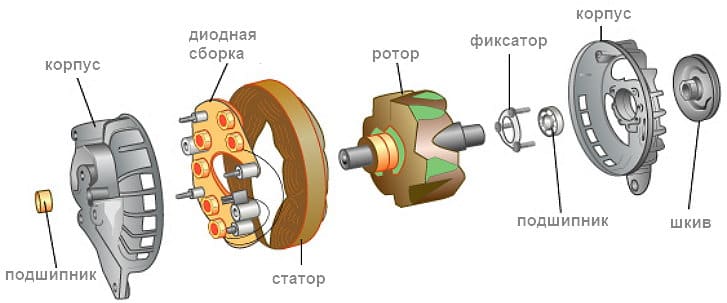
Generator structure: 1.Nut. 2. Washer. 3.Pulley 4.Front cover. 5. Distance ring. 6.Rotor. 7.Stator. 8.Back cover. 9.Casing. 10. Gasket. 11.Protective sleeve. 12. Rectifier unit with capacitor. 13.Latch holder with voltage regulator.
The generator is located at the front of the car engine and is started using the crankshaft. The connection diagram and operating principle of a car generator are the same for any car. There are, of course, some differences, but they are usually associated with the quality of the manufactured product, the power and the layout of the components in the motor. All modern cars are equipped with alternating current generator sets, which include not only the generator itself, but also a voltage regulator. The regulator equally distributes the current in the excitation winding, and it is due to this that the power of the generator set itself fluctuates at a time when the voltage at the power output terminals remains unchanged.
New cars are most often equipped with an electronic unit on the voltage regulator, so the on-board computer can control the amount of load on the generator set. In turn, on hybrid cars the generator performs the work of the starter-generator; a similar circuit is used in other designs of the stop-start system.
The principle of operation of a car generator

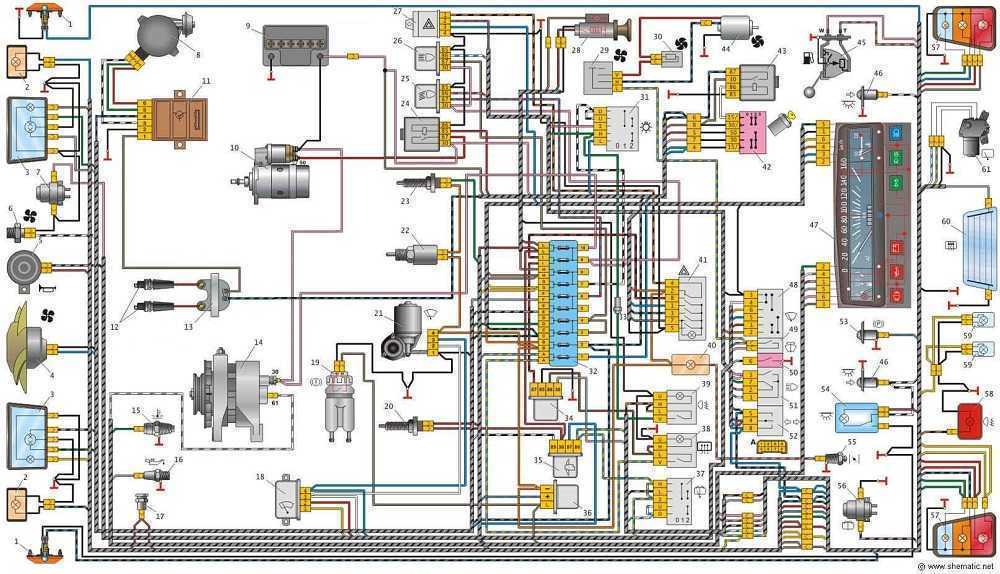
Connection diagram for the VAZ 2110-2115 generator
Generator connection diagram AC includes the following components:
- Battery.
- Generator.
- Fuse block.
- Ignition.
- Dashboard.
- Rectifier block and additional diodes.
The principle of operation is quite simple: when the ignition is turned on plus through the lock, the ignition goes through the fuse box, light bulb, diode bridge and goes through a resistor to minus. When the light on the dashboard lights up, then the plus goes to the generator (to the excitation winding), then during the process of starting the engine, the pulley begins to rotate, the armature also rotates, due to electromagnetic induction, electromotive force is generated and alternating current appears.
The most dangerous thing for the generator is the short circuit of the heat sink plates connected to the “ground” and the “+” terminal of the generator by metal objects accidentally falling between them or conductive bridges formed by contamination.
Next, the diode passes plus into the rectifier block through a sine wave into the left arm, and minus into the right arm. Additional diodes on the light bulb cut off the negatives and only positives are obtained, then it goes to the dashboard assembly, and the diode that is there allows only the negative to pass through, as a result the light goes out and the positive then goes through the resistor and goes to the negative.

The principle of operation of a car DC generator can be explained as follows: a small direct current begins to flow through the excitation winding, which is regulated by the control unit and is maintained by it at a level of slightly more than 14 V. Most generators in a car are capable of generating at least 45 amperes. The generator operates at 3000 rpm and above - if you look at the ratio of the size of the fan belts for the pulleys, it will be two or three to one in relation to the engine frequency.
To avoid this, the plates and other parts of the generator rectifier are partially or completely covered with an insulating layer. The heat sinks are combined into a monolithic design of the rectifier unit mainly by mounting plates made of insulating material, reinforced with connecting bars.
Generator connection diagram for VAZ 2107
The VAZ 2107 charging scheme depends on what type of generator is used. To recharge the battery on cars such as VAZ-2107, VAZ-2104, VAZ-2105, which have a carburetor engine, you will need a G-222 type generator or its equivalent with a maximum output current of 55A. In turn, VAZ-2107 cars with an injection engine use a generator 5142.3771 or its prototype, which is called a high-energy generator, with a maximum output current of 80-90A. It is also possible to install more powerful generators with an output current of up to 100A. Absolutely all types of alternating current generators have built-in rectifier units and voltage regulators; they are usually made in the same housing with brushes or are removable and mounted on the housing itself.
The VAZ 2107 charging circuit has minor differences depending on the year of manufacture of the car. The most important difference is the presence or absence of a charge indicator lamp, which is located on the instrument panel, as well as the method of connecting it and the presence or absence of a voltmeter. Such circuits are mainly used on carburetor cars, while on cars with injection engines the circuit does not change, it is identical to those cars that were manufactured previously.
Generator set designations:
- “Plus” of the power rectifier: “+”, V, 30, V+, WAT.
- “Ground”: “-”, D-, 31, B-, M, E, GRD.
- Excitation winding output: Ш, 67, DF, F, EXC, E, FLD.
- Output for connection to the serviceability lamp: D, D+, 61, L, WL, IND.
- Phase output: ~, W, R, STA.
- Output of the stator winding zero point: 0, MP.
- Output of the voltage regulator for connecting it to the on-board network, usually to the “+” of the battery: B, 15, S.
- Voltage regulator output for powering it from the ignition switch: IG.
- Voltage regulator output for connecting it to the on-board computer: FR, F.

Generator circuit VAZ-2107 type 37.3701
- Accumulator battery.
- Generator.
- Voltage regulator.
- Mounting block.
- Ignition switch.
- Voltmeter.
- Battery charge indicator lamp.
When the ignition is turned on, the plus from the lock goes to fuse No. 10, and then goes to the battery charge indicator lamp relay, then goes to the contact and to the coil output. The second terminal of the coil interacts with the central terminal of the starter, where all three windings are connected. If the relay contacts close, then the control lamp lights up. When the engine starts, the generator generates current and an alternating voltage of 7V appears on the windings. Current passes through the relay coil and the armature begins to attract, and the contacts open. Generator No. 15 passes current through fuse No. 9. Similarly, the excitation winding receives power through the brush voltage generator.
Charging diagram for VAZ with injection engines
This scheme is identical to the schemes on other VAZ models. It differs from the previous ones in the method of exciting and monitoring the serviceability of the generator. It can be carried out using a special control lamp and a voltmeter on the instrument panel. Also, through the charge lamp, the generator is initially excited at the moment it starts working. During operation, the generator operates “anonymously,” that is, excitation comes directly from pin 30. When the ignition is turned on, power through fuse No. 10 goes to the charging lamp in the instrument panel. Then it goes through the mounting block to pin 61. Three additional diodes provide power to the voltage regulator, which in turn transmits it to the excitation winding of the generator. In this case, the indicator lamp will light up. It is at that moment when the generator operates on the plates of the rectifier bridge that the voltage will be much higher than that of the battery. In this case, the control lamp will not light up, because the voltage on its side on the additional diodes will be lower than on the side of the stator winding and the diodes will close. If the control lamp lights up while the generator is running, this may mean that additional diodes are broken.
Checking generator operation
There are several ways to use certain methods, for example: you can check the output current of the generator, the voltage drop on the wire that connects the current output of the generator to the battery, or check the regulated voltage.
To check, you will need a multimeter, a car battery and a lamp with soldered wires, wires for connecting between the generator and the battery, and you can also take a drill with a suitable head, since you may have to twist the rotor by the nut on the pulley.
Basic check with a light bulb and multimeter
Connection diagram: output terminal (B+) and rotor (D+). The lamp must be connected between the main output of the generator B+ and contact D+. After this, we take the power wires and connect the “minus” to the negative terminal of the battery and to the generator ground, the “plus”, respectively, to the plus of the generator and to the B+ output of the generator. We fix it on a vice and connect it.
“Ground” must be connected very last so as not to short-circuit the battery.
We turn on the tester in DC mode, attach one probe to the battery to “plus”, and the second one too, but to “minus”. Next, if everything is in working order, then the light should light up, the voltage in this case will be 12.4V. Then we take a drill and start turning the generator, accordingly, the light bulb will stop burning at this moment, and the voltage will already be 14.9V. Then we add a load, take an H4 hologen lamp and hang it on the battery terminal, it should light up. Then we connect the drill in the same order and the voltage on the voltmeter will show 13.9V. In passive mode, the battery under the light bulb gives 12.2V, and when we turn it with a drill, it gives 13.9V.

Generator test circuit
- Check the functionality of the generator by short circuit, that is, “to spark”.
- It is also undesirable to allow the generator to operate without consumers turned on; it is also undesirable to operate with the battery disconnected.
- Connect terminal “30” (in some cases B+) to ground or terminal “67” (in some cases D+).
- Carry out welding work on the car body with the generator and battery wires connected.
A car generator is one of the key elements of the technical content of a car, the serviceability and accuracy of which directly determines the ability of the car to move. When moving, it recharges the battery and also generates energy that powers various electrical equipment. It is important for the car owner to understand the design features and operating principle of the car generator, its possible malfunctions, as well as how to check it - otherwise there is a risk of being left without a car at the most inopportune moment.
First of all, let’s take a closer look at the functions of a car generator. All modern machines are equipped with an extensive list of electrical equipment that requires a power source. It is also needed for models that do not have any additional peripherals; electricity is required, at a minimum, to start the engine with the starter, create a spark on the candles to ignite the air-fuel mixture, etc. To supply all these consumers, the car uses 2 sources - the battery and the generator.
The battery stores energy and can release it to consuming devices when needed. While the generator produces energy, powers devices and recharges the battery. Thus, if you remove the generator from the structure of the car, it will be able to start and even drive for some time, but after the battery charge is exhausted, the car will stall. It will not be possible to start it again without “lighting it” from another car.
Thus, the main functions of a car generator are:
- battery recharging;
- power supply for electrical equipment installed in the vehicle.
The principle of operation of a car generator
By the nature of its operation, an autogenerator resembles an ordinary electric motor, but the principle of its operation is diametrically opposite: if an ordinary motor converts energy into mechanical movement, then the generator, receiving a rotating impulse from the internal combustion engine, converts it into electricity.
The operating principle of a car generator is approximately the following. After turning the key in the ignition switch, voltage is applied to the rotor winding, it passes through the slip rings and the brush block. As a result, a magnetic field appears around the winding. This field constantly rotates with the motor rotor, while interacting with the stator windings. A current appears on the stator winding, which is supplied to the diode bridge. At the output of the diode bridge, the current already has a stable value. Next, the current is supplied to the voltage regulator, after which it is used to power consumers and the battery.
An important element in the operation of a car generator is the voltage regulator relay. It is necessary to maintain the required current values supplied to the battery. Without the use of a regulator, as the engine speed increased, the alternator would create excess voltage, which could damage the battery. This relay also provides thermal compensation - at low temperatures, increased voltage is supplied to the battery, and as operating temperatures increase, the voltage will decrease.
Signs of a generator malfunction
During the operation of the vehicle, various problems may occur in the generator - mechanical or electrical. The first group includes wear and breakdown of device components, the second group consists of various problems with the winding, brushes, failure of the voltage rectifier, relay regulator, etc.
 You can promptly identify an approaching or already occurring generator breakdown by the following symptoms:
- Difficulty starting the engine. If the generator does not operate in normal mode, the efficiency of battery charging is often impaired. As a result, it receives insufficient or excess charge, as a result of which starting the engine becomes very problematic.
- Dim or flickering light. If, when driving at night, it becomes noticeable that the headlights do not shine brightly enough or the intensity of the light they create changes depending on the level of engine speed, then this indicates that the generator cannot provide the required amount of energy and voltage.
- The "Battery" light on the dashboard came on.. This icon is always illuminated before starting the engine, after which it should go out. However, if it remains on while the engine is running, it indicates that the battery is not charging properly.
- Alternator belt drive is noisy. Many motorists have heard an unpleasant whistle coming from the engine while it has not yet warmed up. It may indicate low tension in the drive belt, which transmits rotation from the engine to the generator rotor. Operating the vehicle in this mode may result in reduced generator efficiency.
- Ringing or unpleasant whistling from the generator housing. Such extraneous sounds indicate wear of the bearings. As a result, the rotor may begin to jam.
How to check a car alternator
If it is better to trust the repair of the generator to professionals, then you can perform the check yourself. The first diagnostic method is using a multimeter:
- Using the device, we measure the voltage at the battery terminals with the engine off - it should be approximately 12.7V;
- We start the engine without giving any gas, turn off all electrical appliances (air conditioning, audio system, etc.);
- We measure the battery voltage again - with the engine running it should be from 13.8 to 14.5 V (on some engines up to 14.8 V);
- We give the load - headlights, air conditioning, audio system, fog lights, etc.;
- We measure the voltage again - it should drop to 13.7-14 V. If the multimeter readings are lower, this indicates that the generator is not working.
You can also check using the “old-fashioned” method. To do this, we start the engine, turn on a small load (for example, headlights) - and, without turning off the ignition, remove the negative terminal from the battery. If the engine does not stall or the headlights do not go out, this means that the generator provides the engine with sufficient energy. If the car stalls after removing the terminal, this indicates a non-working generator.
Video on the topic
The generator is the main source of electricity for the machine. We will tell you in detail how it works, what it consists of and its structure inside. The information is suitable for beginners and experienced car enthusiasts.
How does it work
When starting a car engine, the main consumer of electricity is the starter; the current reaches hundreds of amperes, which causes a significant drop in battery voltage. In this mode, consumers are powered only by the battery, which is rapidly discharged. Immediately after starting the engine, the generator becomes the main source of power supply.The car's generator is a source of constant recharging of the battery while the engine is running. If it doesn't work, the battery will drain quickly. It provides the required current to charge the battery and operate electrical appliances. After recharging the battery, the generator reduces the charging current and operates normally.
When turning on powerful consumers (for example, a rear window defroster, headlights) and low engine speeds, the total current consumption may be greater than the generator is capable of delivering. In this case, the load will fall on the battery and it will begin to discharge.
Drive and mounting
The drive is carried out from the crankshaft pulley by a belt drive. The larger the diameter of the pulley on the crankshaft and the smaller the diameter of the pulley, the higher the speed of the generator, and accordingly, it is able to deliver more current to consumers.On modern machines, the drive is carried out by a poly-V-belt. Due to its greater flexibility, it allows the generator to be fitted with a small diameter pulley and hence high gear ratios. V-belt tension carried out by tension rollers with the generator stationary.
The device and what it consists of
Any car generator contains a stator with a winding, sandwiched between two covers - the front, on the drive side, and the rear, on the slip ring side. The generators are bolted to the front of the engine on special brackets. The mounting feet and tension eye are located on the covers. The covers, cast from aluminum alloys, have ventilation windows through which air is blown by a fan. Generators of a traditional design are equipped with ventilation windows only in the end part, while those of a “compact” design are equipped with ventilation windows on the cylindrical part above the frontal sides of the stator winding.
 A brush assembly, which is combined with a voltage regulator, and a rectifier assembly are attached to the cover on the slip ring side. The covers are usually tightened together with three or four screws, and the stator is sandwiched between the covers, the seating surfaces of which cover the stator along the outer surface.
 Generator stator: 1 - core, 2 - winding, 3 - slot wedge, 4 - slot, 5 - terminal for connection to the rectifier
The stator is made from steel sheets with a thickness of 0.8...1 mm, but more often it is wound “on edge”. When making a stator package by winding, the stator yoke above the grooves usually has projections along which the position of the layers relative to each other is fixed during winding. These protrusions improve stator cooling due to a more developed outer surface.
The need to save metal led to the creation of a stator package design made up of individual horseshoe-shaped segments. The individual sheets of the stator package are fastened together into a monolithic structure by welding or rivets. Almost all mass-produced car generators have 36 slots in which the stator winding is located. The grooves are insulated with film insulation or sprayed with epoxy compound.
 Car generator rotor: a - assembled; b - disassembled pole system; 1,3 - pole halves; 2 - excitation winding; 4 - slip rings; 5 - shaft
A special feature of automobile generators is the type of rotor pole system. It contains two pole halves with protrusions - beak-shaped poles, six on each half. The pole halves are stamped and may have projections. If there are no protrusions when pressed onto the shaft, a bushing with an excitation winding wound on the frame is installed between the pole halves, and winding is carried out after installing the bushing inside the frame.
The rotor shafts are made of mild automatic steel. But when using a roller bearing, the rollers of which operate directly at the end of the shaft on the side of the slip rings, the shaft is made of alloy steel, and the shaft journal is hardened. At the threaded end of the shaft, a groove is cut for the key to attach the pulley.
Many modern designs do not have a key. In this case, the end part of the shaft has a recess or protrusion in the form of a hexagon. This allows you to keep the shaft from turning when tightening the pulley fastening nut, or when disassembling the generator, when it is necessary to remove the pulley and fan.
Brush unit- this is the structure in which the brushes are placed i.e. sliding contacts. There are two types of brushes used in automobile generators - copper-graphite and electrographite. The latter have an increased voltage drop in contact with the ring compared to copper-graphite ones. They provide significantly less wear on the slip rings. The brushes are pressed against the rings by spring force.
 Rectifier units Two types are used. These are either heat sink plates into which the power rectifier diodes are pressed, or structures with highly developed fins and the diodes are soldered to the heat sinks. The diodes of the additional rectifier usually have a cylindrical or pea-shaped plastic housing or are made in the form of a separate sealed block, the inclusion of which is carried out in the circuit by busbars.
The most dangerous is the short circuit of the heat sink plates connected to the “ground” and the “+” terminal of the generator by metal objects accidentally falling between them or conductive bridges formed by contamination, because In this case, a short circuit occurs in the battery circuit and a fire is possible. To avoid this, the plates and other parts of the generator rectifier are partially or completely covered with an insulating layer. The heat sinks are combined into a monolithic design of the rectifier unit mainly by mounting plates made of insulating material, reinforced with connecting bars.
Generator bearing units These are typically deep groove ball bearings with one-time, lifetime grease and one or two-way seals built into the bearing. Roller bearings are used only on the slip ring side and quite rarely, mainly by American companies. The fit of ball bearings on the shaft on the side of the slip rings is usually tight, on the drive side - sliding, in the cover seat, on the contrary - on the side of the slip rings - sliding, on the drive side - tight.
The car generator is cooled by one or two fans mounted on its shaft. In this case, in the traditional design of generators, air is sucked by a centrifugal fan into the cover from the side of the slip rings. For generators that have a brush assembly, a voltage regulator and a rectifier outside the internal cavity and are protected by a casing, air is sucked through the slots of this casing, directing the air to the hottest places - to the rectifier and voltage regulator. 
Cooling system: a - devices of conventional design; b - for increased temperature in the engine compartment; c - devices of compact design. Arrows show the direction of air flows
On cars with a dense engine compartment, generators with a special casing are used, through which cold outside air enters. For generators of a “compact” design, cooling air is taken in from both the rear and front covers.
Why do you need a voltage regulator?
 The regulators maintain the generator voltage within certain limits for optimal operation of electrical appliances included in the vehicle's on-board network. The generators are equipped with semiconductor electronic voltage regulators built inside the housing. Their execution patterns and design may vary, but the principle of operation is the same.
 Voltage regulators have the property of thermal compensation - changing the voltage supplied to the battery, depending on the air temperature in the engine compartment for optimal battery charging. The lower the air temperature, the greater the voltage must be supplied to the battery and vice versa. The thermal compensation value reaches up to 0.01 V per 1°C. Some models of remote regulators have manual voltage level switches (winter/summer).
If you compare a car with a living organism, then its engine acts as a heart, and a generator acts as a nervous system. Will the car be able to move without this unit? Yes, it can, but not for long, not yet. It is the car generator that charges the battery, maintaining the general voltage of the operating network. We will tell you about the principle of operation of the generator and its main elements.
How the unit works

Rotor
This part is essentially an electromagnet with one winding. It is located on the shaft. A special core is attached on top of the winding, the diameter of which is one and a half to two millimeters smaller than the diameter of the starter. The current supply is provided by copper rings. They are also located on the shaft and are connected to the winding with special brushes.
Winding
The starter winding is made of copper wire. It is attached to the grooves of the core. The latter is made in the form of a circle and is made of metal with increased magnetic properties. This material is called transformer iron. Since the generator is three-phase, the starter is equipped with three windings. They are connected to each other and together resemble a triangle.
A rectifier bridge is connected at the point of their connection. The wire from which the winding is made is provided with double heat-resistant insulation. In most cases, a special varnish is used for this.
Relay regulator
Another important element is the relay regulator. It is an electronic circuit and has access to graphite brushes. The relay regulator can be installed in the generator housing or separately from it. In the first case, it is located next to the graphite brushes, and in the second, the brushes are attached to.
Rectifier bridge
The part is formed from six diodes. The latter are located on a conductive base in pairs and combined with each other. At the output, the alternating voltage is converted to direct voltage. The bridge is also called a “horseshoe” due to the fact that in appearance it resembles this product.
The video shows the generator device:
Generator operating principle
The operation of a car generator is based on the principle of formation. This happens in the stator windings. Electrical voltage is generated due to the influence of a constant magnetic field formed around the core. The motor drives the generator rotor using a belt drive. A constant voltage is applied to the winding, which is sufficient to create a magnetic flux.
When the core rotates along the windings, an electromotive force is generated in them. The relay regulator adjusts the strength of the magnetic flux in accordance with the load that is removed from the generator terminal. At the output, a voltage is generated in the range of 13.6–14.2 (this depends on the time of year). This is enough to recharge and keep it constantly charged. The on-board network is also powered from the positive terminal and is connected in parallel with the battery. Regardless of which generator you bought, the device and principle of operation will be the same for all samples. All such units work the same.
The video shows how the generator works:
No car generator can work without. This element ensures the maintenance of a constant voltage, which the unit generates due to the change in current strength that occurs in the windings. If the rotor rotates at a high frequency without a regulator, the voltage can reach a couple of tens of volts. This will lead to burnout of lamps and damage to windings, diodes and other devices.
Types of regulators
By design, voltage regulators are divided into two main categories:
- hybrid;
- integral.
The first group includes regulators, the electronic circuit of which simultaneously uses radioelements and. In modern car models, integral regulators are most often used. All components of such devices (with the exception of the output stage) are made on the basis of thin-film microelectronic technology.

Warning lamp
To avoid problems with the regulator, keep an eye on the warning light. It is located on the dashboard of the car. If the lamp lights up when the generator is running, this indicates a malfunction of the voltage regulator or the unit itself.
Car alternator mounting
The car generator is usually attached to the front of the engine using bolts and special brackets. The covers contain mounting paws and an eyelet for the device. If the generator is attached using two paws, they are located on two engine covers. If only one fastening paw is used, it is placed on only one cover (front). The rear leg usually has a hole in which the spacer is installed. It eliminates the gap formed between the motor bracket and the base of the paw.

Different operating modes of the generator set
In order to understand a car generator, you need to understand its operating modes. The first mode we will consider is the operation of a car generator while starting the engine. When starting the engine, electricity is mainly consumed by the starter. In this mode, the current is very high, and this causes a significant decrease in the voltage at the battery terminal. Thus, electricity consumers are powered only by the battery, which is rapidly discharged.
Immediately after starting the engine, the generator becomes the main source of power. The device provides the current necessary to charge the battery and operate various electrical appliances. After , the charging current level drops. The generator remains the source of electricity.
When powerful consumers of electricity, such as headlight heaters or stove fans, are turned on, the rotor begins to rotate slowly. Then the generator cannot supply as much current as required. In this mode, the load is transferred to the battery, which quickly discharges.
You can replace the generator in a car, but to do this you must follow some rules:
- the new unit must have the same current-speed characteristics as the standard one;
- the energy parameters of the generators must be the same;
- the dimensions of the new generator must be suitable so that it can be easily installed on the motor;
- the units must have the same gear ratios;
- The circuits of both generators must be completely identical.
Keep in mind that generally units installed on foreign cars are attached with only one paw. At the same time, domestic devices are using two paws. Therefore, when replacing a foreign unit with ours, you will have to replace the mounting bracket on the motor.

When installing the battery in a car, you need to make sure that the polarity is connected correctly. If an error occurs, the generator rectifier will be damaged, and this may lead to a fire. The same danger is fraught with starting the motor if the polarity is incorrectly determined.
When operating the machine, you must adhere to the following rules:
- control, monitor the cleanliness of the contacts and the reliability of their connections (if the wire contacts are bad, the on-board voltage is beyond the permissible norm);
- disconnect wires from the car generator and battery when electric welding structural elements;
- make sure that the generator belt is properly tensioned (if it is loosely tensioned, the generator will not be able to work efficiently; if it is too tight, its bearings will wear out quickly);
- If the control lamp gives signals, immediately find out the reason for this.
In the video - generator repair:
Under no circumstances should you do the following:
- leave the car with the battery connected if you suspect that the rectifier is faulty (this will lead to battery discharge and wiring fire);
- check whether the generator is working by connecting its terminals to each other or disconnecting the battery while the engine is running (this can cause the voltage regulator, on-board computer, and electronic elements of the ignition system to break);
- do not allow any remaining antifreeze or other liquid to get on the generator;
- leave the generator on if the battery terminals are removed (this leads to damage to the electrical equipment of the machine and the voltage regulator).
We told you about the main features of the generator. This knowledge will be useful to any driver who strives to understand cars. Remember that a generator is a very complex device, so it is important to treat it with care. Constantly monitor the condition of all its parts, as well as the degree of tension of the drive belt. Then your car generator will be able to serve you for as long as possible.
Please leave a comment about what you read! We are interested in your opinion.
To power the vehicle's on-board network, two current sources are provided. And it is very important for the driver to understand the principles of operation of a car generator, which, along with the battery, is designed to provide energy to the electrical equipment of the car.
Strict requirements are placed on the reliability and stability of devices of this kind.
In the Russian Federation, manufactured and used electrical equipment must comply with GOST R 52230-2004. The document establishes general technical conditions that also apply to car starter batteries. The mentioned national standard fully complies with international standards, which allows the use of foreign-made components on domestic machines.
At the dawn of the automotive industry and until the 60s of the last century, DC generators were used in on-board networks - capricious and low-power. With the advent of semiconductor (selenium and silicon) rectifiers, alternating current units began to be installed on machines. They are three times lighter in weight and, at the same load, provide higher stability of the output current.
Why do you need a generator in a car?
The generator is used to maintain a certain voltage and current in the on-board network. The main purpose of a car generator is to provide stable power to electrical equipment when the engine is running - in particular, for:
- Battery charge.
- Power supply to all electrical consumers under normal conditions.
- Power supply to consumers together with the battery during extreme operation.
The use of a car generator allows you to restore battery charge, which is spent on starting the engine using the starter. In this case, the voltage in the on-board network remains within strictly established limits, exceeding the electrochemical potential of the battery plates.
Having understood the question of why a generator is needed in a car, you need to understand that in the event of a unit failure, the engine will continue to operate for some time using the battery. You can extend this period by turning off all non-essential consumers: heater fan, air conditioner, audio system. When the battery charge is depleted, the engine will stall.
Design and design of a car generator
Three-phase AC electrical units installed on modern machines can be of 2 types: standard and compact. The general structure of car generators of 2 types is the same - they consist of the following elements:
- Pulley with shaft and bearings.
- Rotor with slip rings.
- Stator windings.
- Generator housings.
- Voltage regulator.
- Rectifier device.
- Brush unit.
The designs of automobile generators differ only in their layout features. With the same electrical parameters, standard units are much larger than small ones. Compactness is ensured through the use of modern materials and technologies.

Here's what an electric generator consists of and what functions its components perform:
- The pulley transmits rotation from the crankshaft to the rotor using a belt.
- The generator housing has two covers (front, rear) and is needed to connect the elements into a single structure. On the outer surface there are brackets with which the device is mounted on the engine.
- The rotor is a shaft on which field windings and slip rings made of electrical copper are installed.
- The stator includes a magnetic circuit made of a package of steel plates in which shaped grooves are cut. They contain three-phase windings made of single-core copper wire, where the current is generated.
- The voltage regulator is manufactured as a separate unit or combined with a brush assembly. The main purpose is to control the operation of the generator by changing the current in the excitation winding.
- The rectifier device according to the Larionov scheme consists of two parts: aluminum heat sinks, into each of which three power diodes are pressed. The valves ensure the conversion of alternating voltage to direct voltage, which is used in the on-board network to power electrical equipment.
- The voltage is transferred to the excitation winding through a special unit and cylindrical slip rings. The brushes are made from special grades of graphite and are installed in a holder with guides made of dielectrics. To ensure tight contact, they are spring-loaded, and voltage is supplied to them through a wire pressed into the base.

When understanding the design of a modern car generator, you should distinguish between its mechanical and electrical parts. The first (which includes a pulley and two rotor bearings) ensures its rotation in the housing. The second part actually generates electric current to power the on-board network. The described circuit of a car generator was first used in products of the American company Neuville in 1946. Military vehicles and buses were equipped with such devices.

Basic parameters of the generator
The main nominal parameters are determined based on the technical requirements for the design of a specific vehicle model:
- Voltage. In accordance with GOST 52230-2004, it is selected from the range from 7.14 to 28 V.
- Recoil current.
- Frequency of excitation and self-excitation.
The current-speed characteristic determines the dependence of the rated current of the generator on its rotation frequency. The voltage in the on-board network of passenger cars and commercial vehicles, as well as buses, is 12 V, of particularly powerful and special vehicles - 24 V. The maximum output current is determined at a rotor speed of 6,000 min-1.
Another important characteristic of this unit is efficiency. For modern models this figure is at the level of 50-60%.

How does a car generator work?
The device begins to function only after the engine is started by the starter, which is powered directly from the battery. The key operating principle of a car generator is to convert mechanical energy into electrical energy. A pulley is installed on the crankshaft of the power unit, which spins a rotor mounted on maintenance-free bearings through a belt drive.

The field winding located on the rotating armature is powered from the battery through the brush assembly and slip rings. To protect the battery from self-discharge, the connection is made through a special rectifier consisting of three diodes. The voltage in this circuit is regulated by an electronic or electromechanical stabilizer, integrated or made as a separate device.
The rotating armature creates electromagnetic fields that induce alternating current in the stator windings. It goes to a rectifier, which is a block of diodes. It includes six valves: three negative and three positive. They provide conversion of phase voltage to linear. The generator windings are connected according to a “delta” or “star” circuit. In the first case, the current value is 1.7 times lower than in the second. The triangle is used on high-power car models.
The described operating principle of a car generator ensures that the on-board voltage is maintained in the range from 13.9 to 14.5 V. The exact value depends on the crankshaft speed and load level. Consumers (for example, a battery) are connected to the electric unit via the “B+” terminal.
Why is there a voltage regulator in the generator?
When the speed of the crankshaft and, accordingly, the rotor changes, voltage surges may occur in the on-board network, which negatively affect the work of consumers. Surges are eliminated by limiting the excitation current transmitted through the brushes from the voltage regulator to the rotor. Control is carried out by changing the connection time of the armature winding depending on the load on the on-board network.
If the regulator malfunctions or the brush assembly and slip rings are damaged, the battery may be undercharged or overcharged. Long-term operation of a machine with such a defect will lead to battery failure.
A generator malfunction can be determined by the indicator on the instrument panel. When the battery charge light comes on after starting, it indicates that the voltage in the network is insufficient, while blinking indicates that it is too high.
Conclusion
Even the most general understanding of the structure and operating principles of a car generator can help avoid electrical equipment malfunctions. The generator starts working after the engine starts and serves as the main source of current in the car.
During operation of the vehicle, it is necessary to carefully monitor the tension of the drive belt, which affects the position of the generator. On a number of modern cars, the unit is firmly fixed, and a worn V-belt or poly-V belt must be changed immediately. Maintaining the generator in good condition will avoid large expenses for major car repairs.


