LED flashlight.
http://ua1zh. *****/led_driver/led_driver. htm
Autumn has come, it’s already dark outside, and there are still no light bulbs in the entrance. Screwed it in... The next day - no again. Yes, these are the realities of our lives... I bought a flashlight for my wife, but it turned out to be too big for her purse. I had to do it myself. The scheme does not pretend to be original, but maybe it will work for someone - judging by the Internet forums, interest in such technology is not decreasing. I foresee possible questions - “Isn’t it easier to take a ready-made chip like the ADP1110 and not bother?” Yes, of course, it's much easier
But the cost of this chip in Chip&Dip is 120 rubles, the minimum order is 10 pcs and the execution time is a month. Manufacturing this design took me exactly 1 hour and 12 minutes, including time for prototyping, with a cost of 8 rubles per LED. A self-respecting radio amateur will always find the rest in his trash bin.
Actually the whole scheme:
HHonestly, I will swear if someone asks - on what principle does all this work?
And I will scold you even moreYes, if they ask for a signet...
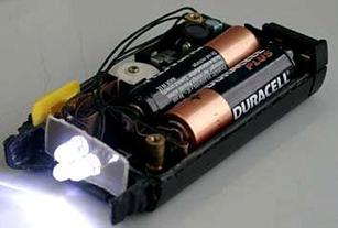
Below is an example of a practical design. For the case, a suitable box from some kind of perfume was taken. If desired, you can make the flashlight even more compact - everything is determined by the housing used. Now I’m thinking about putting a flashlight into the body from a thick marker.
A little about the details: I took the transistor KT645. This one just came to hand. You can experiment with selecting VT1 if you have time and thereby slightly increase the efficiency, but it is unlikely that you can achieve a radical difference with the transistor used. The transformer is wound on a suitable ferrite ring with high permeability with a diameter of 10 mm and contains 2x20 turns of PEL-0.31 wire. The windings are wound with two wires at once, it is possible without twisting - this is not a ShTTL... Rectifier diode - any Schottky, capacitors - tantalum SMD for a voltage of 6 volts. LED - any super-bright white with a voltage of 3-4 volts. When using a battery with a nominal voltage of 1.2 volts as a battery, the current through the LED I had was 18 mA, and when using a dry battery with a nominal voltage of 1.5 volts, it was 22 mA, which provides maximum light output. Overall the device consumed approximately 30-35mA. Considering the occasional use of the flashlight, the battery may well last for a year.
| When battery voltage is applied to the circuit, the voltage drop across resistor R1 in series with the high-brightness LED is 0 V. Therefore, transistor Q2 is off and transistor Q1 is in saturation. The saturated state of Q1 turns on the MOSFET, thereby supplying battery voltage to the LED through the inductance. As the current flowing through resistor R1 increases, this turns on transistor Q2 and turns off transistor Q1 and therefore the MOSFET transistor. During the MOSFET's off state, the inductance continues to provide power to the LED through the Schottky diode D2. The HB LED is a 1 W Lumiled white LED. Resistor R1 helps control the brightness of the LED. Increasing the value of resistor R1 reduces the brightness of the glow. http://www. *****/shem/schematics. html? di=55155 |

Making a modern flashlight
http://www. *****/schemes/contribute/constr/light2.shtml
Rice. 1. Schematic diagram of a current stabilizer
Using the pulse current stabilizer circuit (Fig. 1), long known in amateur radio circles, using modern affordable radio components, you can assemble a very good LED flashlight.
For modification and alteration, the author purchased a mongrel flashlight with a 6 V 4 Ah battery, a “spotlight” on a 4.8 V 0.75 A lamp and a diffused light source on a 4 W LDS. The “original” incandescent light bulb almost immediately turned black due to operation at too high a voltage and failed after several hours of operation. A full battery charge was enough for 4-4.5 hours of operation. Turning on the LDS generally loaded the battery with a current of about 2.5 A, which led to its discharge after 1-1.5 hours.
To improve the flashlight, white LEDs of an unknown brand were purchased on the radio market: one with a beam divergence of 30o and an operating current of 100 mA for the “spotlight”, as well as a dozen matte LEDs with an operating current of 20 mA to replace the LDS. According to the scheme (Fig. 1), a stable current generator was assembled with an efficiency of about 90%. The circuitry of the stabilizer made it possible to use a standard switch to switch the LEDs. The LED2 indicated in the diagram is a battery of 10 parallel connected identical white LEDs, each rated for a current of 20 mA. Parallel connection of LEDs does not seem entirely advisable due to the nonlinearity and steepness of their current-voltage characteristics, but experience has shown that the spread of LED parameters is so small that even with such a connection their operating currents are almost the same. What is important is the complete identity of the LEDs; if possible, they should be purchased “from the same factory packaging.”
After modification, the “spotlight” of course became a little weaker, but it was quite sufficient, the diffused light mode did not visually change. But now, thanks to the high efficiency of the current stabilizer, when using the directional mode, a current of 70 mA is consumed from the battery, and in the diffuse mode, mA, that is, the flashlight can work without recharging for about 50 or 25 hours, respectively. Brightness does not depend on the degree of discharge of the battery due to current stabilization.
The current stabilizer circuit works as follows: When power is applied to the circuit, transistors T1 and T2 are locked, T3 is open, because an unlocking voltage is applied to its gate through resistor R3. Due to the presence of inductor L1 in the LED circuit, the current increases smoothly. As the current in the LED circuit increases, the voltage drop across the R5-R4 chain increases; as soon as it reaches approximately 0.4 V, transistor T2 will open, followed by T1, which in turn will close the current switch T3. The increase in current stops, a self-induction current appears in the inductor, which begins to flow through diode D1 through the LED and a chain of resistors R5-R4. As soon as the current decreases below a certain threshold, transistors T1 and T2 will close, T3 will open, which will lead to a new cycle of energy accumulation in the inductor. In normal mode, the oscillatory process occurs at a frequency of the order of tens of kilohertz.
About the details: there are no special requirements for the parts; you can use any small-sized resistors and capacitors. Instead of the IRF510 transistor, you can use the IRF530, or any n-channel field-effect switching transistor with a current of more than 3 A and a voltage of more than 30 V. Diode D1 must be equipped with a Schottky barrier for a current of more than 1 A; if you install even a regular high-frequency type KD212, the efficiency will decrease up to 75-80%. The inductor can be homemade; it is wound with a wire no thinner than 0.6 mm, or better - a bundle of several thinner wires. About 20-30 turns of wire per armor core B16-B18 are required with a non-magnetic gap of 0.1-0.2 mm or close from 2000NM ferrite. If possible, the thickness of the non-magnetic gap is selected experimentally according to the maximum efficiency of the device. Good results can be obtained with ferrites from imported inductors installed in switching power supplies and also in energy-saving lamps. Such cores have the appearance of a spool of thread and do not require a frame or a non-magnetic gap. Coils on toroidal cores made of pressed iron powder, which can be found in computer power supplies (the output filter inductors are wound on them), work very well. The non-magnetic gap in such cores is evenly distributed throughout the volume due to the production technology.
The same stabilizer circuit can be used in conjunction with other batteries and galvanic cell batteries with a voltage of 9 or 12 volts without any change in the circuit or cell ratings. The higher the supply voltage, the less current the flashlight will consume from the source, its efficiency will remain unchanged. The operating stabilization current is set by resistors R4 and R5. If necessary, the current can be increased to 1 A without the use of heat sinks on the parts, only by selecting the resistance of the setting resistors.
The battery charger can be left “original” or assembled according to any of the known schemes, or even used externally to reduce the weight of the flashlight.
The device is assembled by hanging installation in the free cavities of the flashlight body and filled with hot-melt adhesive for sealing.
It’s also a good idea to add a new device to the flashlight: a battery charge indicator (Fig. 2).
Rice. 2. Schematic diagram of the battery charge level indicator.
The device is essentially a voltmeter with a discrete LED scale. This voltmeter has two operating modes: in the first, it estimates the voltage on the battery being discharged, and in the second, the voltage on the battery being charged. Therefore, in order to correctly assess the degree of charge, different voltage ranges were selected for these operating modes. In the discharge mode, the battery can be considered fully charged when the voltage on it is 6.3 V, when it is completely discharged, the voltage will drop to 5.9 V. In the process of charging the voltages are different, a battery is considered fully charged if the voltage at the terminals is 7, 4 V. In connection with this, an algorithm for the operation of the indicator has been developed: if the charger is not connected, that is, at the “+ Charge” terminal there is no voltage, the “orange” crystals of the two-color LEDs are de-energized and transistor T1 is locked. DA1 generates the reference voltage determined by resistor R8. The reference voltage is supplied to a line of comparators OP1.1 - OP1.4, on which the voltmeter itself is implemented. To see how much charge is left in the battery, you need to press the S1 button. In this case, supply voltage will be supplied to the entire circuit and, depending on the voltage on the battery, a certain number of green LEDs will light up. When fully charged, the entire column of 5 green LEDs will light up; when completely discharged, only one, the lowest LED, will light up. If necessary, the voltage is adjusted by selecting the resistance of resistor R8. If the charger is turned on, through the “+ Charge” terminal and diode D1 supplies voltage to the circuit, including the “orange” parts of the LEDs. In addition, T1 opens and connects resistor R9 in parallel with resistor R8, as a result of which the reference voltage generated by DA1 increases, which leads to a change in the operating thresholds of the comparators - the voltmeter is adjusted to a higher voltage. In this mode, all the time the battery is charging, the indicator displays the charging process also with a column of glowing LEDs, only this time the column is orange.
Homemade LED flashlight
The article is dedicated to radio amateur tourists, and to everyone who has in one way or another encountered the problem of an economical lighting source (for example, a tent at night). Although LED flashlights have not surprised anyone lately, I will still share my experience in creating such a device, and will also try to answer questions from those who want to repeat the design.
Note: The article is intended for “advanced” radio amateurs who are well aware of Ohm’s law and have held a soldering iron in their hands.
The basis was a purchased flashlight "VARTA" powered by two AA batteries:
https://pandia.ru/text/78/440/images/image006_50.jpg" width="600" height="277 src=">
Here's what the assembled diagram looks like:
The reference points are the legs of the DIP chip.
A few explanations to the diagram: Electrolytic capacitors - tantalum CHIP. They have low series resistance, which slightly improves efficiency. Schottky diode - SM5818. The chokes had to be connected in parallel, because there was no suitable rating. Capacitor C2 - K10-17b. LEDs - super bright white L-53PWC "Kingbright". As can be seen in the figure, the entire circuit easily fits into the empty space of the light-emitting unit.
The output voltage of the stabilizer in this connection circuit is 3.3V. Since the voltage drop across the diodes in the nominal current range (15-30mA) is about 3.1V, the extra 200mV had to be sown on a resistor connected in series with the output. In addition, a small series resistor improves load linearity and circuit stability. This is due to the fact that the diode has a negative TCR, and when warmed up, its forward voltage drop decreases, which leads to a sharp increase in the current through the diode when it is powered from a voltage source. There was no need to equalize the currents through parallel-connected diodes - no differences in brightness were observed by eye. Moreover, the diodes were of the same type and taken from the same box.
Now about the design of the light emitter. Perhaps this is the most interesting detail. As can be seen in the photographs, the LEDs in the circuit are not tightly sealed, but are a removable part of the structure. I decided to do this in order not to screw up the flashlight, and if necessary, I could insert an ordinary light bulb into it. As a result of much thought about killing two birds with one stone, this design was born:
|
|


I think that no special explanation is required here. The original light bulb from the same flashlight is gutted, 4 cuts are made in the flange on 4 sides (one was already there). 4 LEDs are arranged symmetrically in a circle with some splay for a larger coverage angle (I had to file them a little at the base). The positive terminals (as it turned out according to the diagram) are soldered onto the base near the cuts, and the negative terminals are inserted from the inside into the central hole of the base, cut off and also soldered. The result is such a “lampodiode”, which takes the place of an ordinary incandescent light bulb.
And finally, about the test results. Half-dead batteries were taken for testing in order to quickly bring them to the finish line and understand what the newly made flashlight is capable of. The battery voltage, load voltage, and load current were measured. The run started with a battery voltage of 2.5V, at which the LEDs no longer light up directly. Stabilization of the output voltage (3.3V) continued until the supply voltage was reduced to ~1.2V. The load current was about 100mA (~ 25mA per diode). Then the output voltage began to decrease smoothly. The circuit has switched to a different operating mode, in which it no longer stabilizes, but outputs everything it can. In this mode, it worked up to a supply voltage of 0.5V! The output voltage dropped to 2.7V, and the current from 100mA to 8mA. The diodes were still on, but their brightness was only enough to illuminate the keyhole in the dark entrance. After this, the batteries practically stopped discharging, because the circuit stopped consuming current. After running the circuit in this mode for another 10 minutes, I became bored and turned it off, because further running was of no interest.
The brightness of the glow was compared with a conventional incandescent light bulb at the same power consumption. A 1V 0.068A light bulb was inserted into the flashlight, which at a voltage of 3.1V consumed approximately the same current as the LEDs (about 100mA). The result is clearly in favor of LEDs.
Part II. A little about efficiency or “There is no limit to perfection.”
More than a month has passed since I assembled my first circuit to power an LED flashlight and wrote about it in the above article. To my surprise, the topic turned out to be very popular, judging by the number of reviews and site visits. Since then I have gained some understanding of the subject :), and I considered it my duty to take the topic more seriously and conduct more thorough research. This idea was also brought to me by communication with people who solved similar problems. I would like to tell you about some new results.
Firstly, I should have immediately measured the efficiency of the circuit, which turned out to be suspiciously low (about 63% with fresh batteries). Secondly, I understood the main reason for such low efficiency. The fact is that those miniature chokes that I used in the circuit have an extremely high ohmic resistance - about 1.5 ohms. There could be no talk of saving electricity with such losses. Thirdly, I discovered that the amount of inductance and output capacitance also affects the efficiency, although not as noticeably.
I somehow didn’t want to use a rod choke of the DM type because of its large size, so I decided to make the choke myself. The idea is simple - you need a low-turn choke, wound with a relatively thick wire, and at the same time quite compact. The ideal solution turned out to be a ring made of µ-permalloy with a permeability of about 50. There are ready-made chokes on sale on such rings, widely used in all kinds of switching power supplies. I had at my disposal such a 10 μG choke, which has 15 turns on the K10x4x5 ring. There was no problem rewinding it. The inductance had to be selected based on the efficiency measurement. In the range of 40-90 µG the changes were very insignificant, less than 40 - more noticeable, and at 10 µG it became very bad. I did not raise it above 90 μH, because the ohmic resistance increased, and the thicker wire “inflated” the dimensions. In the end, more for aesthetic reasons, I settled on 40 turns of PEV-0.25 wire, since they lay evenly in one layer and the result was about 80 μG. The active resistance turned out to be about 0.2 ohms, and the saturation current, according to calculations, was more than 3A, which is enough for the eyes... I replaced the output (and at the same time the input) electrolyte with 100 μF, although without compromising the efficiency it can be reduced to 47 μF. As a result, the design has undergone some changes, which, however, did not prevent it from maintaining its compactness:
Laboratory work" href="/text/category/laboratornie_raboti/" rel="bookmark">laboratory work and took down the main characteristics of the scheme:
| 1. Dependence of the output voltage measured on capacitor C3 on the input. I have taken this characteristic before and I can say that replacing the throttle with a better one gave a more horizontal plateau and a sharp break. |
| 2. It was also interesting to track the change in current consumption as the batteries discharged. The “negativity” of the input resistance, typical of key stabilizers, is clearly visible. The peak consumption occurred at a point close to the reference voltage of the microcircuit. A further drop in voltage led to a decrease in the support, and hence the output voltage. The sharp drop in current consumption on the left side of the graph is caused by the nonlinearity of the I-V characteristics of the diodes. |
| 3. And finally, the promised efficiency. Here it was measured by the final effect, i.e. by the power dissipation on the LEDs. (5 percent is lost on the ballast resistance). The chip manufacturers did not lie - with the correct design it gives the required 87%. True, this is only with fresh batteries. As the current consumption increases, the efficiency naturally decreases. At an extreme point, it generally drops to the level of a steam locomotive. An increase in efficiency with a further decrease in voltage is of no practical value, since the flashlight is already “on its last legs” and shines very weakly. |


Looking at all these characteristics, we can say that the flashlight shines confidently when the supply voltage drops to 1V without a noticeable decrease in brightness, i.e. the circuit actually handles a three-fold voltage drop. An ordinary incandescent light bulb with such a discharge of batteries is unlikely to be suitable for lighting.
If something remains unclear to someone, write. I will respond by letter and/or add to this article.
Vladimir Rashchenko, E-mail: rashenko (at) inp. nsk. su
May, 2003.
Velofara - what's next?
So, first headlight built, tested and tested. What are the future promising directions for LED headlight manufacturing? The first stage will probably be a further increase in capacity. I am planning to build a 10-diode headlight with a switchable 5/10 operating mode. Well, further improvement of quality requires the use of complex microelectronic components. For example, it seems to me that it would be nice to get rid of quenching/equalizing resistors - after all, 30-40% of the energy is lost on them. And I would like to have current stabilization through LEDs, regardless of the discharge level of the source. The best option would be to sequentially switch on the entire chain of LEDs with current stabilization. And in order not to increase the number of series batteries, this circuit also needs to increase the voltage from 3 or 4.5 V to 20-25 V. These are, so to speak, specifications for the development of an “ideal headlight”.
It turned out that specialized ICs are produced specifically to solve such problems. Their area of application is controlling the backlight LEDs of LCD monitors for mobile devices - laptops. cell phones, etc. Dima brought me to this information gdt (at) *****- THANK YOU!
In particular, a line of ICs for various purposes for controlling LEDs is produced by Maxim (Maxim Integrated Products, Inc), on whose website ( http://www.) the article "Solutions for Driving White LEDs" (Apr 23, 2002) was found. Some of these "solutions" are great for bicycle lights:
https://pandia.ru/text/78/440/images/image015_32.gif" width="391" height="331 src=">
Option 1. MAX1848 chip, controlling a chain of 3 LEDs.
https://pandia.ru/text/78/440/images/image017_27.gif" width="477" height="342 src=">
Option 3: Another scheme for switching on feedback is possible - from a voltage divider.
https://pandia.ru/text/78/440/images/image019_21.gif" width="534" height="260 src=">
Option 5. Maximum power, multiple LED strings, MAX1698 chip
current mirror", chip MAX1916.
https://pandia.ru/text/78/440/images/image022_17.gif" width="464" height="184 src=">
Option 8. Chip MAX1759.
https://pandia.ru/text/78/440/images/image024_12.gif" width="496" height="194 src=">
Option 10. MAX619 chip - perhaps. the simplest connection scheme. Operation when the input voltage drops to 2 V. Load 50 mA at Uin>3 V.
https://pandia.ru/text/78/440/images/image026_15.gif" width="499" height="233 src=">
Option 12. The ADP1110 chip is rumored to be more common than MAXs, it works starting from Uin = 1.15 V ( !!! only one battery!!!) Uout. up to 12 V
https://pandia.ru/text/78/440/images/image028_15.gif" width="446" height="187 src=">
Option 14. Microcircuit LTC1044 - a very simple connection diagram, Uin = from 1.5 to 9 V; Uout = up to 9 V; load up to 200mA (but, however, typical 60 mA)
As you can see, all this looks very tempting :-) All that remains is to find these microcircuits inexpensively somewhere....
Hooray! Found ADP1rub. with VAT) We are building a new powerful headlight!
10 LEDs, switchable 6\10, five chains of two.
|
|
|


MAX1848 White LED Step-Up Converter to SOT23
MAX1916 Low-Dropout, Constant-Current Triple White LED Bias Supply
Display Drivers and Display Power Application Notes and Tutorials
Charge Pump Versus Inductor Boost Converter for White LED Backlights
Buck/Boost Charge-Pump Regulator Powers White LEDs from a Wide 1.6V to 5.5V Input
Analog ICs for 3V Systems
On the Rainbow Tech website: Maxim: DC-DC conversion devices(pivot table)
On the Premier Electric website: Pulse regulators and controllers for power supply without galvanics. interchanges(pivot table)
On the Averon website - microcircuits for power supplies(Analog Devices) - summary table
Powering LEDs with ZXSC300
The feasibility of using LEDs in flashlights, bicycle lights, and local and emergency lighting devices today is beyond doubt. The light output and power of LEDs is growing, and their prices are falling. There are more and more light sources that use white LEDs instead of the usual incandescent lamp and it is not difficult to buy them. Shops and markets are filled with LED products made in China. But the quality of these products leaves much to be desired. Therefore, there is a need to modernize affordable (primarily priced) LED light sources. Yes, and replacing incandescent lamps with LEDs in high-quality Soviet-made flashlights also makes sense. I hope that the following information will not be superfluous.
As is known, an LED has a nonlinear current-voltage characteristic with a characteristic “heel” in the initial section.
Rice. 1 Volt-ampere characteristics of a white LED. As we can see, the LED begins to glow if a voltage of more than 2.7 V is applied to it. When powered by a galvanic or rechargeable battery, the voltage of which gradually decreases during operation, the brightness of the radiation will vary widely. To avoid this, it is necessary to power the LED with a stabilized current. And the current must be rated for this type of LED. Typically for standard 5 mm LEDs it averages 20 mA. For this reason, it is necessary to use electronic current stabilizers, which limit and stabilize the current flowing through the LED. It is often necessary to power an LED from one or two batteries with a voltage of 1.2 - 2.5 V. For this, step-up voltage converters are used. Since any LED is essentially a current device, from an energy efficiency standpoint it is advantageous to provide direct control of the current flowing through it. This eliminates losses that occur on the ballast (current-limiting) resistor. One of the optimal options for powering various LEDs from autonomous current sources of low voltage 1-5 volts is to use a specialized ZXSC300 microcircuit from ZETEX. ZXSC300 is a pulsed (inductive) DC-DC boost converter with pulse frequency modulation. Let's look at the operating principle of the ZXSC300. On the image Fig.2 shows one of the typical schemes for powering a white LED with pulsed current using the ZXSC300. The pulsed power supply mode of the LED allows you to make the most efficient use of the energy available in the battery or accumulator.
In addition to the ZXSC300 microcircuit itself, the converter contains: a 1.5 V battery, a storage choke L1, a power switch - transistor VT1, a current sensor - R1. The converter works in its traditional way. For some time, due to the pulse coming from generator G (via the driver), transistor VT1 is open and the current through inductor L1 increases linearly. The process lasts until the voltage drop across the current sensor - low-resistance resistor R1 reaches 19 mV. This voltage is enough to switch the comparator (the second input of which is supplied with a small reference voltage from the divider). The output voltage from the comparator is supplied to the generator, as a result of which the power switch VT1 closes and the energy accumulated in the inductor L1 enters the LED VD1. Then the process is repeated. Thus, fixed portions of energy are supplied to the LED from the primary power source, which it converts into light. Energy management occurs using pulse-frequency modulation PFM (PFM Pulse Frequency Modulation). The principle of PFM is that the frequency changes, but the duration of the pulse or pause, respectively, the open (On-Time) and closed (Off-Time) state of the key remains constant. In our case, the Off-Time remains unchanged, i.e. the pulse duration at which the external transistor VT1 is in the closed state. For the ZXSC300 controller, Toff is 1.7 µs. This time is enough to transfer the accumulated energy from the inductor to the LED. The duration of the pulse Ton, during which VT1 is open, is determined by the value of the current-measuring resistor R1, the input voltage, and the difference between the input and output voltage, and the energy that accumulates in the inductor L1 will depend on its value. It is considered optimal when the total period T is 5 µs (Toff + Ton). The corresponding operating frequency is F=1/5μs =200 kHz. With the element ratings indicated in the diagram in Fig. 2, the oscillogram of the voltage pulses on the LED looks like
Fig.3 type of voltage pulses on the LED. (grid 1V/div, 1μs/div) A little more detail about the parts used.Transistor VT1 - FMMT617, n-p-n transistor with a guaranteed collector-emitter saturation voltage of no more than 100 mV at a collector current of 1 A. Capable of withstanding pulsed collector current up to 12 A (constant 3 A), collector-emitter voltage 18 V, coefficient current transmission 150...240. Dynamic characteristics of the transistor: on/off time 120/160 ns, f = 120 MHz, output capacitance 30 pF. FMMT617 is the best switching device that can be used with ZXSC300. It allows you to obtain high conversion efficiency with an input voltage of less than one volt.
Storage choke L1. Both industrial SMD Power Inductor and homemade ones can be used as a storage choke. Choke L1 must withstand the maximum current of power switch VT1 without saturating the magnetic circuit. The active resistance of the inductor winding should not exceed 0.1 Ohm, otherwise the efficiency of the converter will noticeably decrease. Ring magnetic cores (K10x4x5) from power filter chokes used in old computer motherboards are well suited as a core for self-winding. Today, used computer hardware can be purchased at bargain prices on any radio market. And hardware is an inexhaustible source of various parts for radio amateurs. When winding yourself, you will need an inductance meter for control. Current measuring resistor R1. Low-resistance resistor R1 47 mOhm is obtained by parallel connection of two SMD resistors of standard size 1206, 0.1 Ohm each. LED VD1. White LED VD1 with a rated operating current of 150 mA. The author's design uses two four-crystal LEDs connected in parallel. The rated current of one of them is 100 mA, the other 60 mA. The operating current of the LED is determined by passing a stabilized direct current through it and monitoring the temperature of the cathode (negative) terminal, which is a radiator and removes heat from the crystal. At the rated operating current, the temperature of the heat sink should not exceed degrees. Instead of one VD1 LED, you can also use eight standard 5 mm LEDs connected in parallel with a current of 20 mA. Appearance of the device
Shown in Fig. 5 Rice. 5(size 14 by 17 mm). When developing boards for such devices, it is necessary to strive for the minimum values of capacitance and inductance of the conductor connecting K VT1 with the storage choke and LED, as well as for the minimum inductance and active resistance of the input and output circuits and the common wire. The resistance of the contacts and wires through which the supply voltage is supplied should also be minimal. In the following diagrams Fig. 6 and Fig. Figure 7 shows a method for powering high-power Luxeon type LEDs with a rated operating current of 350 mA Rice. 6 Power supply method for high-power Luxeon LEDs Rice. 7 The method of powering high-power LEDs of the Luxeon type - ZXSC300 is powered from the output voltage. Unlike the previously discussed circuit, here the LED is powered not pulsed, but direct current. This makes it easy to control the operating current of the LED and the efficiency of the entire device. Feature of the converter in Fig. 7 is that ZXSC300 is powered by output voltage. This allows the ZXSC300 to operate (after startup) when the input voltage drops down to 0.5 V. The VD1 diode is a Schottky diode designed for a current of 2A. Capacitors C1 and C3 are ceramic SMD, C2 and C3 are tantalum SMD. Number of LEDs connected in series. | Resistance of the current measuring resistor, mOhm. | Inductance of storage choke, μH. |
||||


Today, powerful 3 - 5 W LEDs from various manufacturers (both famous and not so famous) have become available for use.

And in this case, the use of ZXSC300 makes it possible to easily solve the problem of efficiently powering LEDs with an operating current of 1 A or more.

It is convenient to use an n-channel (operating from 3 V) Power MOSFET as a power switch in this circuit; you can also use an assembly of the FETKY MOSFET series (with a Schottky diode in one SO-8 package).
With the ZXSC300 and a few LEDs, you can easily breathe new life into your old flashlight. The FAR-3 battery flashlight was modernized.

Fig.11
LEDs were used 4-crystal with a rated current of 100 mA - 6 pcs. Connected in series by 3. To control the light flux, two converters on the ZXSC300 are used, with independent on/off. Each converter operates on its own triple LED.

Fig.12
The converter boards are made on double-sided fiberglass, the second side is connected to the power supply minus.

Fig.13

Fig.14
The FAR-3 flashlight uses three sealed batteries NKGK-11D (KCSL 11) as batteries. The nominal voltage of this battery is 3.6 V. The final voltage of a discharged battery is 3 V (1 V per cell). Further discharge is undesirable because it will shorten the battery life. And further discharge is possible - the converters on the ZXSC300 operate, as we remember, down to 0.9 V.
Therefore, to control the voltage on the battery, a device was designed, the circuit of which is shown in Fig. 15.

Fig.15
This device uses inexpensive, readily available components. DA1 - LM393 is a well-known dual comparator. A reference voltage of 2.5 V is obtained using TL431 (analogue of KR142EN19). The response voltage of the comparator DA1.1, about 3 V, is set by the divider R2 - R3 (selection of these elements may be required for accurate operation). When the voltage on battery GB1 drops to 3 V, the red LED HL1 lights up, if the voltage is more than 3 V, then HL1 goes out and the green LED HL2 lights up. Resistor R4 determines the hysteresis of the comparator.
The control circuit board is shown in Rice. 16 ( size 34 by 20 mm).

If you have any difficulties purchasing the ZXSC300 microcircuit, FMMT617 transistor or low-resistance SMD resistors 0.1 Ohm, you can contact the author by e-mail david_ukr (at) *****
You can purchase the following components (delivery by mail)
Elements | Quantity | Price, $ | Price, UAH |
|
Chip ZXSC 300 + transistor FMMT 617 | ||||
Resistor 0.1 Ohm SMD size 0805 | ||||
Printed circuit board Fig. 8 |
- Download article in PDF format- 1.95MB Download the article in DjVU format(What is this?
Making your own LED flashlight
Suitable for various powers. The luminous efficiency of the device should not exceed 80 lm. You should also pay attention to the driver. Typically it is installed with an output capacitor. Some models have an amplifier. On average, their current consumption is 3 A.
If we consider sensitive modifications, then they have a voltage surge protection system installed. In order to understand the issue in more detail, it is necessary to consider specific models.
Circuits with capacitive capacitors
LED flashlight circuits with capacitors include wave filters. In this case, triggers are used on a semiconductor basis. As a rule, their output voltage does not exceed 20 V. Converters are used to reduce sensitivity. Drivers for models are installed with different throughputs. If we consider a 30 V LED, then it has a transceiver.

Using snubber capacitors
The LED circuit with a damping capacitor includes contact filters. In total, the models have two converters. The driver is connected to the LED through a winding. Some modifications have a compact transceiver. Most often it is used with an amplifier.
Characteristics of LED marked 530
These are universal for flashlights too. The characteristics of the devices indicate a high conductivity coefficient. LEDs are produced for 20 and 25 V. If we consider the first option, the luminous efficiency of the device is on average 60 lm. The color rendering coefficient in this case depends on the conductivity of the transceiver. For many models, the amplifier is used without a converter.
The current consumption of LEDs does not exceed 2.5 A. The turn-on time for models of this type is about 6 ms. If we consider 25 V LEDs, then they only use a pulse transceiver. Many models have one amplifier. The driver is connected using a converter. The luminous flux parameter is around 65 lm. The turn-on time for LEDs of this type is 7 ms.
LED 640 (LEDs for flashlights): characteristics, photos
The LED circuit of this series includes a phase-type converter. Filters are used to increase sensitivity. Amplifiers are most often used on a magnetic basis. The luminous efficiency parameter in the devices is 65 lm. It is also important to note that the current consumption does not exceed 4.2 A. The frequency deviation averages 4 Hz.
The service life of this type of LED is three years. The disadvantages of the devices include the low current conductivity of the drivers. Their brightness indicator is extremely low. Light output, as a rule, does not exceed 5%. These 6 volt flashlight LEDs work well.

Using LED 765
The 12V unit uses the specified flashlight LEDs. The 2014 specifications indicate an increased level of current consumption. this modification is equal to 45 lm. It is also important to note that the model is suitable for switching amplifiers. The driver in the device is used at 6.5 microns. Phase interference with these LEDs is not a problem.
Luminous efficiency averages 70 lm. The service life of the device does not exceed four years. The color rendering coefficient is 80%. The model is perfect for flashlights with regulators. In this case, the devices are connected via a contact adapter.
LED 840 circuit
These are compact and universal LEDs for flashlights. The characteristics of the model primarily indicate a high dispersion rate. Its pulsation coefficient reaches a maximum of 80%. The device turn-on time is 5 ms. According to experts, the model is excellent for 12 V flashlights. The amplifier in the device is of the absorbing type.
In total, the model has two drivers. The LED trigger is used with an adapter. To solve problems with heat loss, a capacitor is used as standard. The luminous efficiency of the presented model is 67 lm. The conductivity indicator does not exceed 10 microns. In this case, the current consumption is 0.3. The minimum permissible LED temperature is only -10 degrees. The model does not have an overheating protection system.
Characteristics of LED 827
Models with are suitable for the indicated LEDs for flashlights. The characteristics of the device indicate the presence of high-quality wired transceivers. The amplifiers of the model are installed in an open type. The device uses two capacitors in total. They do an excellent job of minimizing heat loss. The minimum permissible LED temperature is -15 degrees.
They are not suitable for 15V flashlights. The protection system in the device is used with filters. The model has a driver for 4.5 microns. Current consumption is no more than 4 A. The LED turn-on time is on average 6 ms. The pulsation coefficient of the model is 85%. Luminous efficiency, as a rule, does not exceed 50 lm.
LED 830
These flashlight LEDs are perfect for 10V devices. Their characteristics are quite good. The turn-on time is 5 ms, the luminous efficiency is 65 lm, and the current consumption is 3.3 A. The model uses a phase-type converter. According to experts, the model is not suitable for 15 V flashlights.
There is no transceiver in the indicated LED. The driver itself is installed with a conductivity of 4.5 microns. Problems with current rectification are solved thanks to capacitors. The pulsation coefficient of the model reaches a maximum of 90%. The service life of the presented device is three years. The minimum permissible LED temperature does not exceed -20 degrees.

Characteristics of LED series LB
The specified LED is suitable for 15 V flashlights. The characteristics of the model indicate an increased color rendering coefficient. The output voltage of the model is 15 V. The filter in the device is of the wave type. The driver in this case is connected via a conductor. The LED transceiver is used with an adapter. The capacitor is installed in an open type. The model has two triggers in total. In this case, the energy consumption is 2.5 A.
The luminous flux of the device reaches a maximum of 65 lm. The pulsation coefficient of the model is insignificant. Also, the disadvantages can be attributed to the low level of the minimum permissible temperature. A Chinese LED flashlight turns on in 4 ms. The model rarely has problems with current rectification. This model is not suitable for 10V flashlights. The LED does not have an overheating protection system. The frequency deviation of the model is 5 Hz. These Cree flashlight LEDs work great.

daylight
These LEDs for flashlights are produced with high-quality pulse-type amplifiers. In total, the model has two capacitors. The transceiver is standard wired type. It is also important to note that the maximum frequency deviation is 4 Hz. The current consumption of the LED does not exceed 3 A. The luminous flux of the device is 70 lm. The light output of the model is insignificant.
According to experts, the model is excellent for 12 V flashlights. The driver is directly connected via an adapter. On average, the turn-on time is 6 ms. The service life of the presented model is 5 years. The minimum permissible LED temperature is -15 degrees.

TB series (warm white light)
These are simple and inexpensive LEDs for flashlights. The characteristics of the device indicate that the color rendering coefficient of the model is low. It is also important to note that the output voltage is 8 V. The LED lifespan is three years. The transceiver of the modification is used with high sensitivity. In total, the model has two capacitors. According to experts, the device is not suitable for 10 V flashlights. The current consumption of the model is 2 A. The LED luminous flux reaches a maximum of 65 lm.

Problems with negative modulation are rare. The disadvantages include only a small conductivity parameter. Filters in the device are used only of the open type. The maximum frequency deviation of the LED reaches 5 Hz. To reduce the sensitivity, a trigger is used on the capacitor. The pulsation coefficient of the model is insignificant. To install the LED, a wire adapter is required.
Features of LED models of the LHB series (cold white light)
These LEDs have good characteristics. First of all, it is important to note that the color rendering coefficient is 80%. In this case, the service life is three years. The direct output voltage is 12 V. The turn-on time is 5 ms. In this case, the amplifier is used with an adapter. According to experts, problems with heat loss are rare. The model's capacitors are of the pass-through type.
At the moment, it is not worth seriously considering lanterns with incandescent lamps: one of the main characteristics of any lantern is efficiency, and in this regard LEDs there are no equals. However, LEDs are different from LEDs, especially when it comes to powerful models. The fact is that powerful LEDs heat up quite noticeably, and overheating is literally like death for them: the rate of crystal degradation increases significantly. For cheap LEDs of unknown origin, the parameters even in the same series are seriously different, and in two externally identical flashlights, one will heat up, while the other will work without problems - and you are unlikely to like playing the lottery. Serious manufacturers (the undisputed authority here is Cree) provide much more accurate control of product parameters, and their crystals themselves have a considerable resource.
Best power supply, if you do not plan to use the flashlight for a long time in the cold, these are lithium-ion and lithium-polymer batteries, which have the best capacity-to-weight ratio at the moment. Although they are more expensive than regular batteries, the ability to quickly charge quickly makes up for the difference in prices. If the flashlight will be used frequently, it is better to choose a model with quick-change 18650 batteries and an external charger; for occasional use, models with built-in USB charging are more convenient.
With the need for hull strength and especially protective glass, it’s hard to argue. It’s no wonder that American Maglite flashlights have earned popularity, as they can really work like a baton without the risk of damaging the flashlight itself. But, naturally, a flashlight with such dimensions is not always convenient, but modern tactical flashlights can be considered real all-rounders: they are compact (here the combination of LEDs with a lithium battery again demonstrates all its best sides), durable, and their dust and moisture protection is not an option, but norm. Therefore, they can be used even on a hike, even in the garage, or just carried “just in case” in your pocket. The main thing is to take into account the diameter of the flashlight body, since most barrel mounts are designed for diameters of 22 mm (7/8 inch) and 25 mm (1 inch).
Additional options will also not be superfluous: for example, why separately carry an external battery for gadgets on a hike, if you can buy a flashlight with the function of recharging external devices? Well, a flashlight with an adjustable focus and a removable diffuser will serve both as a search spotlight and as a source of diffused light in the camp, if you turn down the brightness to minimum.
For comparison brightness a visual indicator is the maximum luminous flux, which is usually measured in lumens. Visual references are car headlights, which are also focused light sources: a regular halogen will produce about 1200 lumens, while xenon can provide 4000 lumens.
Making your own LED flashlight
LED flashlight with 3-volt converter to LED 0.3-1.5V 0.3-1.5
VLEDFlashLight
Typically, a blue or white LED requires 3 - 3.5v to operate; this circuit allows you to power a blue or white LED with low voltage from one AA battery.Normally, if you want to light up a blue or white LED you need to provide it with 3 - 3.5 V, like from a 3 V lithium coin cell.
Details:
Light-emitting diode
Ferrite ring (~10 mm diameter)
Wire for winding (20 cm)
1kOhm resistor
N-P-N transistor
Battery
Parameters of the transformer used:
The winding going to the LED has ~45 turns, wound with 0.25mm wire.
The winding going to the base of the transistor has ~30 turns of 0.1mm wire.
The base resistor in this case has a resistance of about 2K.
Instead of R1, it is advisable to install a tuning resistor, and achieve a current through the diode of ~22 mA; with a fresh battery, measure its resistance, then replacing it with a constant resistor of the obtained value.
The assembled circuit should work immediately.
There are only 2 possible reasons why the scheme will not work.
1. the ends of the winding are mixed up.
2. too few turns of the base winding.
Generation disappears with the number of turns<15.
 Place the wire pieces together and wrap them around the ring.
Connect the two ends of different wires together.
The circuit can be placed inside a suitable housing.
The introduction of such a circuit into a flashlight operating on 3V significantly extends the duration of its operation from one set of batteries.
Option to make the flashlight powered by one 1.5V battery.

The transistor and resistance are placed inside the ferrite ring


The white LED runs on a dead AAA battery.
Modernization option "flashlight - pen"
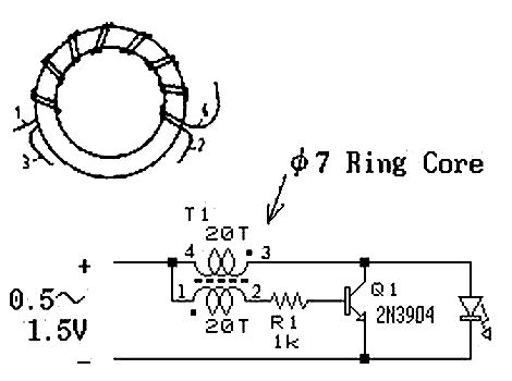
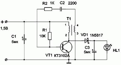
 The excitation of the blocking oscillator shown in the diagram is achieved by transformer coupling at T1. The voltage pulses arising in the right (according to the circuit) winding are added to the voltage of the power source and are supplied to the LED VD1. Of course, it would be possible to eliminate the capacitor and resistor in the base circuit of the transistor, but then failure of VT1 and VD1 is possible when using branded batteries with low internal resistance. The resistor sets the operating mode of the transistor, and the capacitor passes the RF component.
The circuit used a KT315 transistor (as the cheapest, but any other with a cutoff frequency of 200 MHz or more) and a super-bright LED were used. To make a transformer, you will need a ferrite ring (approximate size 10x6x3 and permeability of about 1000 HH). The wire diameter is about 0.2-0.3 mm. Two coils of 20 turns each are wound on the ring.
If there is no ring, then you can use a cylinder of similar volume and material. You just have to wind 60-100 turns for each of the coils.
Important point : you need to wind the coils in different directions.
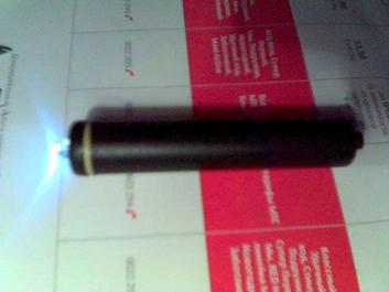
Photos of the flashlight:
the switch is in the "fountain pen" button, and the gray metal cylinder conducts current.

We make a cylinder according to the standard size of the battery.


It can be made from paper, or use a piece of any rigid tube.
We make holes along the edges of the cylinder, wrap it with tinned wire, and pass the ends of the wire into the holes. We fix both ends, but leave a piece of conductor at one end so that we can connect the converter to the spiral.
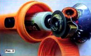
A ferrite ring would not fit into the lantern, so a cylinder made of a similar material was used.

A cylinder made from an inductor from an old TV.
The first coil is about 60 turns.
Then the second one swings in the opposite direction again for 60 or so. The coils are held together with glue.
Assembling the converter:

Everything is located inside our case: We solder the transistor, the capacitor, the resistor, solder the spiral on the cylinder, and the coil. The current in the coil windings must go in different directions! That is, if you wound all the windings in one direction, then swap the leads of one of them, otherwise generation will not occur.
The result is the following:

We insert everything inside, and use nuts as side plugs and contacts.
We solder the coil leads to one of the nuts, and the VT1 emitter to the other. Glue it. We mark the conclusions: where we have the output from the coils we put “-”, where the output from the transistor with the coil we put “+” (so that everything is like in a battery).
Now you need to make a “lampodiode”.

Attention: There should be a minus LED on the base.
Assembly:
 As is clear from the figure, the converter is a “substitute” for the second battery. But unlike it, it has three points of contact: with the plus of the battery, with the plus of the LED, and the common body (through the spiral).
Its location in the battery compartment is specific: it must be in contact with the positive of the LED.
Modern flashlightwith LED operating mode powered by constant stabilized current.

The current stabilizer circuit works as follows:
When power is applied to the circuit, transistors T1 and T2 are locked, T3 is open, because an unlocking voltage is applied to its gate through resistor R3. Due to the presence of inductor L1 in the LED circuit, the current increases smoothly. As the current in the LED circuit increases, the voltage drop across the R5-R4 chain increases; as soon as it reaches approximately 0.4V, transistor T2 will open, followed by T1, which in turn will close the current switch T3. The increase in current stops, a self-induction current appears in the inductor, which begins to flow through diode D1 through the LED and a chain of resistors R5-R4. As soon as the current decreases below a certain threshold, transistors T1 and T2 will close, T3 will open, which will lead to a new cycle of energy accumulation in the inductor. In normal mode, the oscillatory process occurs at a frequency of the order of tens of kilohertz.
About details:
Instead of the IRF510 transistor, you can use the IRF530, or any n-channel field-effect switching transistor with a current of more than 3A and a voltage of more than 30 V.
Diode D1 must have a Schottky barrier for a current of more than 1A; if you install even a regular high-frequency type KD212, the efficiency will drop to 75-80%.
The inductor is homemade; it is wound with a wire no thinner than 0.6 mm, or better - with a bundle of several thinner wires. About 20-30 turns of wire per armor core B16-B18 are required with a non-magnetic gap of 0.1-0.2 mm or close from 2000NM ferrite. If possible, the thickness of the non-magnetic gap is selected experimentally according to the maximum efficiency of the device. Good results can be obtained with ferrites from imported inductors installed in switching power supplies, as well as in energy-saving lamps. Such cores have the appearance of a spool of thread and do not require a frame or a non-magnetic gap. Coils on toroidal cores made of pressed iron powder, which can be found in computer power supplies (the output filter inductors are wound on them), work very well. The non-magnetic gap in such cores is evenly distributed throughout the volume due to the production technology.
The same stabilizer circuit can be used in conjunction with other batteries and galvanic cell batteries with a voltage of 9 or 12 volts without any change in the circuit or cell ratings. The higher the supply voltage, the less current the flashlight will consume from the source, its efficiency will remain unchanged. The operating stabilization current is set by resistors R4 and R5.
If necessary, the current can be increased to 1A without the use of heat sinks on the parts, only by selecting the resistance of the setting resistors.
The battery charger can be left “original” or assembled according to any of the known schemes, or even used externally to reduce the weight of the flashlight.
LED flashlight from calculator B3-30
The converter is based on the circuit of the B3-30 calculator, the switching power supply of which uses a transformer only 5 mm thick and having two windings. Using a pulse transformer from an old calculator made it possible to create an economical LED flashlight.
The result is a very simple circuit.
 The voltage converter is made according to the circuit of a single-cycle generator with inductive feedback on transistor VT1 and transformer T1. The pulse voltage from winding 1-2 (according to the circuit diagram of the B3-30 calculator) is rectified by diode VD1 and supplied to the ultra-bright LED HL1. Capacitor C3 filter. The design is based on a Chinese-made flashlight designed to install two AA batteries. The converter is mounted on a printed circuit board made of one-sided foil fiberglass 1.5 mm thickFig.2dimensions that replace one battery and are inserted into the flashlight instead. A contact made of double-sided foil-coated fiberglass with a diameter of 15 mm is soldered to the end of the board marked with a “+” sign; both sides are connected by a jumper and tinned with solder.
After installing all the parts on the board, the “+” end contact and the T1 transformer are filled with hot-melt adhesive to increase strength. A variant of the lantern layout is shown inFig.3and in a particular case depends on the type of flashlight used. In my case, no modifications to the flashlight were required, the reflector has a contact ring to which the negative terminal of the printed circuit board is soldered, and the board itself is attached to the reflector using hot-melt adhesive. The printed circuit board assembly with the reflector is inserted instead of one battery and clamped with a lid.
 The voltage converter uses small-sized parts. Resistors type MLT-0.125, capacitors C1 and C3 are imported, up to 5 mm high. Diode VD1 type 1N5817 with a Schottky barrier; in its absence, you can use any rectifier diode that has suitable parameters, preferably germanium due to the lower voltage drop across it. A correctly assembled converter does not need adjustment unless the transformer windings are reversed; otherwise, swap them. If the above transformer is not available, you can make it yourself. Winding is carried out on a ferrite ring of standard size K10*6*3 with a magnetic permeability of 1000-2000. Both windings are wound with PEV2 wire with a diameter of 0.31 to 0.44 mm. The primary winding has 6 turns, the secondary winding has 10 turns. After installing such a transformer on the board and checking its functionality, it should be secured to it using hot-melt adhesive.
Tests of a flashlight with an AA battery are presented in Table 1.
During testing, the cheapest AA battery was used, costing only 3 rubles. The initial voltage under load was 1.28 V. At the output of the converter, the voltage measured on the super-bright LED was 2.83 V. The LED brand is unknown, diameter 10 mm. The total current consumption is 14 mA. The total operating time of the flashlight was 20 hours of continuous operation.
When the battery voltage drops below 1V, the brightness drops noticeably.
| Time, h | V battery, V | V conversion, V |
| 0 | 1,28 | 2,83 |
| 2 | 1,22 | 2,83 |
| 4 | 1,21 | 2,83 |
| 6 | 1,20 | 2,83 |
| 8 | 1,18 | 2,83 |
| 10 | 1,18 | 2.83 |
| 12 | 1,16 | 2.82 |
| 14 | 1,12 | 2.81 |
| 16 | 1,11 | 2.81 |
| 18 | 1,11 | 2.81 |
| 20 | 1,10 | 2.80 |
Homemade LED flashlight
The basis is a VARTA flashlight powered by two AA batteries:
Since diodes have a highly nonlinear current-voltage characteristic, it is necessary to equip the flashlight with a circuit for working with LEDs, which will ensure constant brightness as the battery discharges and will remain operational at the lowest possible supply voltage.
The basis of the voltage stabilizer is a micro-power step-up DC/DC converter MAX756.
According to the stated characteristics, it operates when the input voltage is reduced to 0.7V.
Connection diagram - typical:

 Installation is carried out using a hinged method.
Electrolytic capacitors - tantalum CHIP. They have low series resistance, which slightly improves efficiency. Schottky diode - SM5818. The chokes had to be connected in parallel, because there was no suitable denomination. Capacitor C2 - K10-17b. LEDs - super bright white L-53PWC "Kingbright".
As can be seen in the figure, the entire circuit easily fits into the empty space of the light-emitting unit.
The output voltage of the stabilizer in this circuit is 3.3V. Since the voltage drop across the diodes in the nominal current range (15-30mA) is about 3.1V, the extra 200mV had to be extinguished by a resistor connected in series with the output.
In addition, a small series resistor improves load linearity and circuit stability. This is due to the fact that the diode has a negative TCR, and when warmed up, its forward voltage drop decreases, which leads to a sharp increase in the current through the diode when it is powered from a voltage source. There was no need to equalize the currents through parallel-connected diodes - no differences in brightness were observed by eye. Moreover, the diodes were of the same type and taken from the same box.
Now about the design of the light emitter. As can be seen in the photographs, the LEDs in the circuit are not tightly sealed, but are a removable part of the structure.

 The original light bulb is gutted, and 4 cuts are made in the flange on 4 sides (one was already there). 4 LEDs are arranged symmetrically in a circle. The positive terminals (according to the diagram) are soldered onto the base near the cuts, and the negative terminals are inserted from the inside into the central hole of the base, cut off and also soldered. “Lampodiode” is inserted in place of a regular incandescent light bulb.
Testing:
Stabilization of the output voltage (3.3V) continued until the supply voltage was reduced to ~1.2V. The load current was about 100mA (~ 25mA per diode). Then the output voltage began to decrease smoothly. The circuit has switched to a different operating mode, in which it no longer stabilizes, but outputs everything it can. In this mode, it worked up to a supply voltage of 0.5V! The output voltage dropped to 2.7V, and the current from 100mA to 8mA.
A little about efficiency.
 The efficiency of the circuit is about 63% with fresh batteries. The fact is that the miniature chokes used in the circuit have an extremely high ohmic resistance - about 1.5 ohms
The solution is a ring made of µ-permalloy with a permeability of about 50.
40 turns of PEV-0.25 wire, in one layer - it turned out to be about 80 μG. The active resistance is about 0.2 Ohm, and the saturation current, according to calculations, is more than 3A. We change the output and input electrolyte to 100 μF, although without compromising efficiency it can be reduced to 47 μF.
LED flashlight circuiton a DC/DC converter from Analog Device - ADP1110.

Standard typical ADP1110 connection circuit.
This converter chip, according to the manufacturer’s specifications, is available in 8 versions:
| Model | Output voltage |
| ADP1110AN | Adjustable |
| ADP1110AR | Adjustable |
| ADP1110AN-3.3 | 3.3V |
| ADP1110AR-3.3 | 3.3V |
| ADP1110AN-5 | 5 V |
| ADP1110AR-5 | 5 V |
| ADP1110AN-12 | 12 V |
| ADP1110AR-12 | 12 V |
Microcircuits with the indices “N” and “R” differ only in the type of housing: R is more compact.
If you bought a chip with index -3.3, you can skip the next paragraph and go to the “Details” item.
If not, I present to your attention another diagram:

It adds two parts that make it possible to obtain the required 3.3 volts at the output to power the LEDs.
The circuit can be improved by taking into account that LEDs require a current source rather than a voltage source to operate. Changes in the circuit so that it produces 60mA (20 for each diode), and the voltage of the diodes will be set to us automatically, the same 3.3-3.9V.

resistor R1 is used to measure current. The converter is designed in such a way that when the voltage at the FB (Feed Back) pin exceeds 0.22V, it will stop increasing the voltage and current, which means the resistance value R1 is easy to calculate R1 = 0.22V/In, in our case 3.6 Ohm. This circuit helps stabilize the current and automatically select the required voltage. Unfortunately, the voltage will drop across this resistance, which will lead to a decrease in efficiency, however, practice has shown that it is less than the excess that we chose in the first case. I measured the output voltage and it was 3.4 - 3.6V. The parameters of the diodes in such a connection should also be as identical as possible, otherwise the total current of 60 mA will not be distributed equally between them, and again we will get different luminosities.
Details
1. Any choke from 20 to 100 microhenry with a small (less than 0.4 Ohm) resistance is suitable. The diagram shows 47 µH. You can make it yourself - wind about 40 turns of PEV-0.25 wire on a ring of µ-permalloy with a permeability of about 50, size 10x4x5.
2. Schottky diode. 1N5818, 1N5819, 1N4148 or similar. Analog Device DOES NOT RECOMMEND the use of 1N4001
3. Capacitors. 47-100 microfarads at 6-10 volts. It is recommended to use tantalum.
4. Resistors. With a power of 0.125 watts and a resistance of 2 ohms, possibly 300 kohms and 2.2 kohms.
5. LEDs. L-53PWC - 4 pieces.
Voltage converter for powering the DFL-OSPW5111P white LED with a brightness of 30 cd at a current of 80 mA and a radiation pattern width of about 12°.

The current consumed from a 2.41V battery is 143mA; in this case, a current of about 70 mA flows through the LED at a voltage of 4.17 V. The converter operates at a frequency of 13 kHz, the electrical efficiency is about 0.85.
Transformer T1 is wound on a ring magnetic core of standard size K10x6x3 made of 2000NM ferrite.
The primary and secondary windings of the transformer are wound simultaneously (i.e., in four wires).
The primary winding contains - 2x41 turns of wire PEV-2 0.19,
The secondary winding contains 2x44 turns of PEV-2 0.16 wire.
After winding, the terminals of the windings are connected in accordance with the diagram.
Transistors KT529A of the p-n-p structure can be replaced with KT530A of the n-p-n structure, in this case it is necessary to change the polarity of the connection of the battery GB1 and the LED HL1.
The parts are placed on the reflector using wall-mounted installation. Please ensure that there is no contact between the parts and the tin plate of the flashlight, which supplies the minus of the GB1 battery. The transistors are fastened together with a thin brass clamp, which provides the necessary heat removal, and then glued to the reflector. The LED is placed instead of the incandescent lamp so that it protrudes 0.5... 1 mm from the socket for its installation. This improves heat dissipation from the LED and simplifies its installation.
When first turned on, power from the battery is supplied through a resistor with a resistance of 18...24 Ohms so as not to damage the transistors if the terminals of transformer T1 are incorrectly connected. If the LED does not light, it is necessary to swap the extreme terminals of the primary or secondary winding of the transformer. If this does not lead to success, check the serviceability of all elements and correct installation.
Voltage converter for powering an industrial LED flashlight.

Voltage converter to power LED flashlight
 The diagram is taken from the Zetex manual on the use of ZXSC310 microcircuits.
ZXSC310- LED driver chip.
FMMT 617 or FMMT 618.
Schottky diode- almost any brand.
Capacitors C1 = 2.2 µF and C2 = 10 µFfor surface mounting, 2.2 µF is the value recommended by the manufacturer, and C2 can be supplied from approximately 1 to 10 µF
68 microhenry inductor at 0.4 A
 The inductance and resistor are installed on one side of the board (where there is no printing), all other parts are installed on the other. The only trick is to make a 150 milliohm resistor. It can be made from 0.1 mm iron wire, which can be obtained by unraveling the cable. The wire should be annealed with a lighter, thoroughly wiped with fine sandpaper, the ends should be tinned and a piece about 3 cm long should be soldered into the holes on the board. Next, during the setup process, you need to measure the current through the diodes, move the wire, while simultaneously heating the place where it is soldered to the board with a soldering iron.
Thus, something like a rheostat is obtained. Having achieved a current of 20 mA, the soldering iron is removed and the unnecessary piece of wire is cut off. The author came up with a length of approximately 1 cm.
Flashlight on the power source

Rice. 3.Flashlight on a current source, with automatic equalization of current in LEDs, so that LEDs can have any range of parameters (LED VD2 sets the current, which is repeated by transistors VT2, VT3, so the currents in the branches will be the same)
The transistors, of course, should also be the same, but the spread of their parameters is not so critical, so you can take either discrete transistors, or if you can find three integrated transistors in one package, their parameters are as identical as possible. Play around with the placement of the LEDs, you need to choose an LED-transistor pair so that the output voltage is minimal, this will increase the efficiency.
The introduction of transistors leveled out the brightness, however, they have resistance and the voltage drops across them, which forces the converter to increase the output level to 4V. To reduce the voltage drop across the transistors, you can propose the circuit in Fig. 4, this is a modified current mirror, instead of the reference voltage Ube = 0.7V in the circuit in Fig. 3, you can use the 0.22V source built into the converter, and maintain it in the VT1 collector using an op-amp, also built into the converter.

Rice. 4.Flashlight on a current source, with automatic current equalization in LEDs, and with improved efficiency
Because The op-amp output is of the “open collector” type; it must be “pulled up” to the power supply, which is done by resistor R2. Resistances R3, R4 act as a voltage divider at point V2 by 2, so the opamp will maintain a voltage of 0.22*2 = 0.44V at point V2, which is 0.3V less than in the previous case. It is not possible to take an even smaller divider in order to lower the voltage at point V2. a bipolar transistor has a resistance Rke and during operation the voltage Uke will drop on it, in order for the transistor to work correctly V2-V1 must be greater than Uke, for our case 0.22V is quite enough. However, bipolar transistors can be replaced by field-effect transistors, in which the drain-source resistance is much lower, this will make it possible to reduce the divider, so as to make the difference V2-V1 very insignificant.
Throttle.The choke must be taken with minimal resistance, special attention should be paid to the maximum permissible current; it should be about 400 -1000 mA.
The rating doesn't matter as much as the maximum current, so Analog Devices recommends something between 33 and 180 µH. In this case, theoretically, if you do not pay attention to the dimensions, then the greater the inductance, the better in all respects. However, in practice this is not entirely true, because we do not have an ideal coil, it has active resistance and is not linear, in addition, the key transistor at low voltages will no longer produce 1.5A. Therefore, it is better to try several coils of different types, designs and different ratings in order to choose the coil with the highest efficiency and the lowest minimum input voltage, i.e. a coil with which the flashlight will glow for as long as possible.
Capacitors.C1 can be anything. It is better to take C2 with tantalum because It has low resistance, which increases efficiency.
Schottky diode.Any for current up to 1A, preferably with minimal resistance and minimal voltage drop.
Transistors.Any with a collector current of up to 30 mA, coefficient. current amplification of about 80 with a frequency of up to 100 MHz, KT318 is suitable.
LEDs.You can use white NSPW500BS with a glow of 8000 mcd from Power Light Systems.
Voltage transformerADP1110, or its replacement ADP1073, to use it, the circuit in Fig. 3 will need to be changed, take a 760 µH inductor, and R1 = 0.212/60mA = 3.5 Ohm.
Flashlight on ADP3000-ADJ
Options:
Power supply 2.8 - 10 V, efficiency approx. 75%, two brightness modes - full and half.
The current through the diodes is 27 mA, in half-brightness mode - 13 mA.
In order to obtain high efficiency, it is advisable to use chip components in the circuit.
A correctly assembled circuit does not need adjustment.
The disadvantage of the circuit is the high (1.25V) voltage at the FB input (pin 8).
Currently, DC/DC converters with an FB voltage of about 0.3V are produced, in particular from Maxim, on which it is possible to achieve an efficiency above 85%.

Flashlight diagram for Kr1446PN1.

Resistors R1 and R2 are a current sensor. Operational amplifier U2B - amplifies the voltage taken from the current sensor. Gain = R4 / R3 + 1 and is approximately 19. The gain required is such that when the current through resistors R1 and R2 is 60 mA, the output voltage turns on transistor Q1. By changing these resistors, you can set other stabilization current values.
In principle, there is no need to install an operational amplifier. Simply, instead of R1 and R2, one 10 Ohm resistor is placed, from it the signal through a 1 kOhm resistor is supplied to the base of the transistor and that’s it. But. This will lead to a decrease in efficiency. On a 10 Ohm resistor at a current of 60 mA, 0.6 Volt - 36 mW - is dissipated in vain. If an operational amplifier is used, the losses will be:
on a 0.5 Ohm resistor at a current of 60 mA = 1.8 mW + consumption of the op-amp itself is 0.02 mA let at 4 Volts = 0.08 mW
= 1.88 mW - significantly less than 36 mW.
About the components.
Any low-power op-amp with a low minimum supply voltage can work in place of the KR1446UD2; the OP193FS would be better suited, but it is quite expensive. Transistor in SOT23 package. A smaller polar capacitor - type SS for 10 Volts. The inductance of CW68 is 100 μH for a current of 710 mA. Although the cutoff current of the inverter is 1 A, it works fine. It achieved the best efficiency. I selected the LEDs based on the most equal voltage drop at a current of 20 mA. The flashlight is assembled in a housing for two AA batteries. I shortened the space for the batteries to fit the size of AAA batteries, and in the freed-up space I assembled this circuit using wall-mounted installation. A case that fits three AA batteries works well. You will need to install only two, and place the circuit in place of the third.
Efficiency of the resulting device.
Input U I P Output U I P Efficiency
Volt mA mW Volt mA mW %
3.03 90 273 3.53 62 219 80
1.78 180 320 3.53 62 219 68
1.28 290 371 3.53 62 219 59
Replacing the bulb of the “Zhuchek” flashlight with a module from the companyLuxeonLumiledLXHL-NW 98.
We get a dazzlingly bright flashlight, with a very light press (compared to a light bulb).


Rework scheme and module parameters.
StepUP DC-DC converters ADP1110 converters from Analog devices.


Power supply: 1 or 2 1.5V batteries, operability maintained up to Uinput = 0.9V
Consumption:
*with switch open S1 = 300mA
*with switch closed S1 = 110mA
LED Electronic Flashlight
Powered by just one AA or AAA AA battery on a microcircuit (KR1446PN1), which is a complete analogue of the MAX756 (MAX731) microcircuit and has almost identical characteristics.

The flashlight is based on a flashlight that uses two AA size AA batteries as a power source.
The converter board is placed in the flashlight instead of the second battery. A contact made of tinned sheet metal is soldered at one end of the board to power the circuit, and at the other there is an LED. A circle made of the same tin is placed on the LED terminals. The diameter of the circle should be slightly larger than the diameter of the reflector base (0.2-0.5 mm) into which the cartridge is inserted. One of the diode leads (negative) is soldered to the circle, the second (positive) goes through and is insulated with a piece of PVC or fluoroplastic tube. The purpose of the circle is twofold. It provides the structure with the necessary rigidity and at the same time serves to close the negative contact of the circuit. The lamp with the socket is removed from the lantern in advance and a circuit with an LED is placed in its place. Before installation on the board, the LED leads are shortened in such a way as to ensure a tight, play-free fit. Typically, the length of the leads (excluding soldering to the board) is equal to the length of the protruding part of the fully screwed-in lamp base.
The connection diagram between the board and the battery is shown in Fig. 9.2.
Next, the lantern is assembled and its functionality is checked. If the circuit is assembled correctly, then no settings are required.
The design uses standard installation elements: capacitors of the K50-35 type, EC-24 chokes with an inductance of 18-22 μH, LEDs with a brightness of 5-10 cd with a diameter of 5 or 10 mm. Of course, it is possible to use other LEDs with a supply voltage of 2.4-5 V. The circuit has sufficient power reserve and allows you to power even LEDs with a brightness of up to 25 cd!
About some test results of this design.
The flashlight modified in this way worked with a “fresh” battery without interruption, in the on state, for more than 20 hours! For comparison, the same flashlight in the “standard” configuration (that is, with a lamp and two “fresh” batteries from the same batch) worked for only 4 hours.
And one more important point. If you use rechargeable batteries in this design, it is easy to monitor the state of their discharge level. The fact is that the converter on the KR1446PN1 microcircuit starts stably at an input voltage of 0.8-0.9 V. And the glow of the LEDs is consistently bright until the voltage on the battery reaches this critical threshold. The lamp will, of course, still burn at this voltage, but we can hardly talk about it as a real light source.
Rice. 9.2Figure 9.3


The printed circuit board of the device is shown in Fig. 9.3, and the arrangement of elements is in Fig. 9.4.
Turning the flashlight on and off with one button

The circuit is assembled using a CD4013 D-trigger chip and an IRF630 field-effect transistor in the “off” mode. the current consumption of the circuit is practically 0. For stable operation of the D-trigger, a filter resistor and capacitor are connected to the input of the microcircuit; their function is to eliminate contact bounce. It is better not to connect unused pins of the microcircuit anywhere. The microcircuit operates from 2 to 12 volts; any powerful field-effect transistor can be used as a power switch, because The drain-source resistance of the field-effect transistor is negligible and does not load the output of the microcircuit.
CD4013A in SO-14 package, analogue of K561TM2, 564TM2
Simple generator circuits.
 Allows you to power an LED with an ignition voltage of 2-3V from 1-1.5V. Short pulses of increased potential unlock the p-n junction. The efficiency of course decreases, but this device allows you to “squeeze” almost its entire resource from an autonomous power source.
Wire 0.1 mm - 100-300 turns with a tap from the middle, wound on a toroidal ring.


LED flashlight with adjustable brightness and Beacon mode
 The power supply of the microcircuit - generator with adjustable duty cycle (K561LE5 or 564LE5) that controls the electronic key, in the proposed device is carried out from a step-up voltage converter, which allows the flashlight to be powered from one 1.5 galvanic cell.
The converter is made on transistors VT1, VT2 according to the circuit of a transformer self-oscillator with positive current feedback.
The generator circuit with adjustable duty cycle on the K561LE5 chip mentioned above has been slightly modified in order to improve the linearity of current regulation.
The minimum current consumption of a flashlight with six super-bright white LEDs L-53MWC from Kingbnght connected in parallel is 2.3 mA. The dependence of the current consumption on the number of LEDs is directly proportional.
The "Beacon" mode, when the LEDs flash brightly at a low frequency and then go out, is implemented by setting the brightness control to maximum and turning the flashlight on again. The desired frequency of light flashes is adjusted by selecting the capacitor SZ.
The performance of the flashlight is maintained when the voltage is reduced to 1.1v, although the brightness is significantly reduced
A field-effect transistor with an insulated gate KP501A (KR1014KT1V) is used as an electronic switch. According to the control circuit, it matches well with the K561LE5 microcircuit. The KP501A transistor has the following limit parameters: drain-source voltage - 240 V; gate-source voltage - 20 V. drain current - 0.18 A; power - 0.5 W
It is permissible to connect transistors in parallel, preferably from the same batch. Possible replacement - KP504 with any letter index. For IRF540 field-effect transistors, the supply voltage of the DD1 microcircuit. generated by the converter must be increased to 10 V
In a flashlight with six L-53MWC LEDs connected in parallel, the current consumption is approximately equal to 120 mA when the second transistor is connected in parallel to VT3 - 140 mA
Transformer T1 is wound on a ferrite ring 2000NM K10-6"4.5. The windings are wound in two wires, with the end of the first winding connected to the beginning of the second winding. The primary winding contains 2-10 turns, the secondary - 2 * 20 turns. Wire diameter - 0.37 mm. grade - PEV-2. The inductor is wound on the same magnetic circuit without a gap with the same wire in one layer, the number of turns is 38. The inductance of the inductor is 860 μH


Converter circuit for LED from 0.4 to 3V- runs on one AAA battery. This flashlight increases the input voltage to the desired voltage using a simple DC-DC converter.


The output voltage is approximately 7 W (depending on the voltage of the installed LEDs).
Building the LED Head Lamp


As for the transformer in the DC-DC converter. You must do it yourself. The image shows how to assemble the transformer.

Another option for converters for LEDs _http://belza.cz/ledlight/ledm.htm


Flashlight with lead-acid sealed battery with charger.
Lead acid sealed batteries are the cheapest currently available. The electrolyte in them is in the form of a gel, so the batteries allow operation in any spatial position and do not produce any harmful fumes. They are characterized by great durability if deep discharge is not allowed. Theoretically, they are not afraid of overcharging, but this should not be abused. Rechargeable batteries can be recharged at any time without waiting for them to be completely discharged.
Lead-acid sealed batteries are suitable for use in portable flashlights used in the household, in summer cottages, and in production.

Fig.1. Electric flashlight circuit
The electrical circuit diagram of a flashlight with a charger for a 6-volt battery, which makes it possible in a simple way to prevent deep discharge of the battery and, thus, increase its service life, is shown in the figure. It contains a factory-made or home-made transformer power supply and a charging and switching device mounted in the flashlight body.
In the author's version, a standard unit intended for powering modems is used as a transformer unit. The output alternating voltage of the unit is 12 or 15 V, the load current is 1 A. Such units are also available with built-in rectifiers. They are also suitable for this purpose.
The alternating voltage from the transformer unit is supplied to the charging and switching device, which contains a plug for connecting the charger X2, a diode bridge VD1, a current stabilizer (DA1, R1, HL1), a battery GB, a toggle switch S1, an emergency switch S2, an incandescent lamp HL2. Each time the toggle switch S1 is turned on, the battery voltage is supplied to relay K1, its contacts K1.1 close, supplying current to the base of transistor VT1. The transistor turns on, passing current through the HL2 lamp. Turn off the flashlight by switching toggle switch S1 to its original position, in which the battery is disconnected from the winding of relay K1.
The permissible battery discharge voltage is selected at 4.5 V. It is determined by the switching voltage of relay K1. You can change the permissible value of the discharge voltage using resistor R2. As the resistor value increases, the permissible discharge voltage increases, and vice versa. If the battery voltage is below 4.5 V, the relay will not turn on, therefore, no voltage will be supplied to the base of the transistor VT1, which turns on the HL2 lamp. This means the battery needs charging. At a voltage of 4.5 V, the illumination produced by the flashlight is not bad. In case of emergency, you can turn on the flashlight at low voltage with the S2 button, provided that you first turn on the S1 toggle switch.
A constant voltage can also be supplied to the input of the charger-switching device, without paying attention to the polarity of the connected devices.
To switch the flashlight to charging mode, you need to connect the X1 socket of the transformer block to the X2 plug located on the flashlight body, and then connect the plug (not shown in the figure) of the transformer block to a 220 V network.
In this embodiment, a battery with a capacity of 4.2 Ah is used. Therefore, it can be charged with a current of 0.42 A. The battery is charged using direct current. The current stabilizer contains only three parts: an integrated voltage stabilizer DA1 type KR142EN5A or imported 7805, an LED HL1 and a resistor R1. The LED, in addition to working as a current stabilizer, also serves as an indicator of the battery charging mode.
Setting up the flashlight's electrical circuit comes down to adjusting the battery charging current. The charging current (in amperes) is usually chosen to be ten times less than the numerical value of the battery capacity (in ampere-hours).
To configure it, it is best to assemble the current stabilizer circuit separately. Instead of a battery load, connect an ammeter with a current of 2...5 A to the connection point between the cathode of the LED and resistor R1. By selecting resistor R1, set the calculated charge current using the ammeter.
Relay K1 – reed switch RES64, passport RS4.569.724. The HL2 lamp consumes approximately 1A current.
The KT829 transistor can be used with any letter index. These transistors are composite and have a high current gain of 750. This should be taken into account in case of replacement.
In the author's version, the DA1 chip is installed on a standard finned radiator with dimensions of 40x50x30 mm. Resistor R1 consists of two 12 W wirewound resistors connected in series.
Scheme:


LED FLASHLIGHT REPAIR
 Part ratings (C, D, R)
C = 1 µF. R1 = 470 kOhm. R2 = 22 kOhm.
1D, 2D - KD105A (permissible voltage 400V, maximum current 300 mA.)
Provides:
charging current = 65 - 70mA.
voltage = 3.6V.

LED-Treiber PR4401 SOT23


Here you can see what the results of the experiment led to.
The circuit presented to your attention was used to power an LED flashlight, recharge a mobile phone from two metal hydrite batteries, and when creating a microcontroller device, a radio microphone. In each case, the operation of the circuit was flawless. The list where you can use the MAX1674 can go on for a long time.
The easiest way to get a more or less stable current through an LED is to connect it to an unstabilized power supply circuit through a resistor. It must be taken into account that the supply voltage must be at least twice the operating voltage of the LED. The current through the LED is calculated by the formula:
I led = (Umax. power supply - U working diode) : R1
This scheme is extremely simple and in many cases is justified, but it should be used where there is no need to save electricity and there are no high requirements for reliability.
More stable circuits based on linear stabilizers:
It is better to choose adjustable or fixed voltage stabilizers as stabilizers, but it should be as close as possible to the voltage on the LED or a chain of series-connected LEDs.
Stabilizers like LM 317 are very suitable.
German text:
iel war es, mit nur einer NiCd-Zelle (AAA, 250mAh) eine der neuen ultrahellen LEDs mit 5600mCd zu betreiben. Diese LEDs benötigen 3.6V/20mA. Ich habe Ihre Schaltung zunächst unverändert übernommen, als Induktivität hatte ich allerdings nur eine mit 1,4mH zur Hand. Die Schaltung lief auf Anhieb! Allerdings ließ die Leuchtstärke doch noch zu wünschen übrig. Mehr zufällig stellte ich fest, dass die LED extrem heller wurde, wenn ich ein Spannungsmessgerät parallel zur LED schaltete!??? Tatsächlich waren es nur die Messschnüre, bzw. deren Kapazität, die den Effekt bewirkten. Mit einem Oszilloskop konnte ich dann feststellen, dass in dem Moment die Frequenz stark anstieg. Hm, also habe ich den 100nF-Kondensator gegen einen 4.7nF Typ ausgetauscht und schon war die Helligkeit wie gewünscht. Anschließend habe ich dann nur noch durch Ausprobieren die beste Spule aus meiner Sammlung gesucht... Das beste Ergebnis hatte ich mit einem alten Sperrkreis für den 19KHz Pilotton (UKW), aus dem ich die Kreiskapazität entfernt habe. Und hier ist sie nun, die Mini-Taschenlampe:
Sources:
http://pro-radio.ru/
http://radiokot.ru/
Since the invention of electric lighting, scientists have been creating more and more economical sources. But a real breakthrough in this area was the invention of LEDs, which are not inferior in luminous flux to their predecessors, but consume many times less electricity. Their creation, from the first indicator element to the brightest “Cree” diode to date, was preceded by a huge amount of work. Today we will try to analyze the various characteristics of LEDs, find out how these elements have evolved and how they are classified.
Read in the article:
Operating principle and design of light diodes
LEDs are distinguished from conventional lighting devices by the absence of a filament, a fragile bulb and gas in it. This is a fundamentally different element from them. Scientifically speaking, the glow is created due to the presence of p- and n-type materials in it. The former accumulate a positive charge, and the latter accumulate a negative charge. P-type materials accumulate electrons, while n-type materials form holes (places where electrons are missing). At the moment an electric charge appears on the contacts, they rush to the p-n junction, where each electron is injected into the p-type. From the side of the reverse, negative n-type contact, as a result of such movement, a glow occurs. It is caused by the release of photons. However, not all photons emit light visible to the human eye. The force that makes the electrons move is called LED current.
This information is of no use to the average person. It is enough to know that the LED has a durable body and contacts, of which there can be from 2 to 4, and also that each LED has its own nominal voltage required for lighting.

Good to know! The connection is always made in the same order. This means that if you connect “+” to the “-” contact on the element, then there will be no glow - p-type materials simply will not be able to charge, which means there will be no movement towards the transition.
Classification of LEDs by their field of application
Such elements can be indicator and lighting. The former were invented before the latter, and they have long been used in radio electronics. But with the advent of the first lighting LED, a real breakthrough in electrical engineering began. The demand for lighting devices of this type is steadily growing. But progress does not stand still - new types are being invented and put into production, which become brighter without consuming more energy. Let's look in more detail at what LEDs are.
Indicator LEDs: a little history
The first such red LED was created in the middle of the twentieth century. Although it had low energy efficiency and emitted a dim glow, the direction turned out to be promising and developments in this area continued. In the 70s, green and yellow elements appeared, and work to improve them did not stop. By the year 90, the strength of their luminous flux reaches 1 Lumen.

The year 1993 was marked by the appearance in Japan of the first blue LED, which was much brighter than its predecessors. This meant that now, by combining three colors (which make up all the shades of the rainbow), you can get any color. In the early 2000s, the luminous flux already reached 100 Lumens. Nowadays, LEDs continue to improve, increasing brightness without increasing power consumption.
Use of LEDs in household and industrial lighting
Now such elements are used in all industries, be it machine or automotive manufacturing, lighting of production workshops, streets or apartments. If we take the latest developments, we can say that even the characteristics of LEDs for flashlights are sometimes not inferior to old 220 V halogen lamps. Let's try to give one example. If we take the characteristics of a 3 W LED, they will be comparable to the data of an incandescent lamp with a consumption of 20-25 W. The result is energy savings of almost 10 times, which, with daily constant use in an apartment, provides a very significant benefit.

What are the benefits of LEDs and are there any disadvantages to them?
A lot can be said about the positive qualities of light diodes. The main ones include:
As for the negative aspects, there are only two of them:
- Work only with constant voltage;
- It follows from the first - the high cost of lamps based on them due to the need to use (an electronic stabilizing unit).

What are the main characteristics of LEDs?
When choosing such elements for a particular purpose, everyone pays attention to their technical data. The main things you should pay attention to when purchasing devices based on them:
- consumption current;
- Rated voltage;
- power consumption;
- color temperature;
- luminous flux strength.
This is what we can see on the marking. In fact, there are much more characteristics. Let's talk about them now.
LED current consumption - what is it?
The LED consumption current is 0.02 A. But this only applies to elements with one crystal. There are also more powerful light diodes, which can contain 2, 3 or even 4 crystals. In this case, the current consumption will increase, a multiple of the number of chips. It is this parameter that dictates the need to select a resistor that is soldered at the input. In this case, the LED resistance prevents the high current from instantly burning the LED element. This may happen due to high mains current.

Rated voltage
The voltage of an LED is directly dependent on its color. This happens due to the difference in the materials used to make them. Let's consider this dependence.
| LED color | Material | Forward voltage at 20 mA | |
|---|---|---|---|
| Typical value (V) | Range (V) |
||
| IR | GaAs, GaAlAs | 1,2 | 1,1-1,6 |
| Red | GaAsP, GaP, AlInGaP | 2,0 | 1,5-2,6 |
| Orange | GaAsP, GaP, AlGaInP | 2,0 | 1,7-2,8 |
| Yellow | GaAsP, AlInGaP, GaP | 2,0 | 1,7-2,5 |
| Green | GaP, InGaN | 2,2 | 1,7-4,0 |
| Blue | ZnSe, InGaN | 3,6 | 3,2-4,5 |
| White | Blue/UV diode with phosphor | 3,6 | 2,7-4,3 |
Light diode resistance
The same LED itself can have different resistance. It changes depending on its inclusion in the circuit. In one direction - about 1 kOhm, in the other - several MOhms. But there is a nuance here. LED resistance is nonlinear. This means that it can change depending on the voltage applied to it. The higher the voltage, the lower the resistance will be.

Light output and beam angle
The angle of the luminous flux of LEDs may vary, depending on their shape and material of manufacture. It cannot exceed 120 0. For this reason, if greater dispersion is required, special reflectors and lenses are used. This quality of “directional light” contributes to the greatest luminous flux, which can reach 300-350 lm for one 3 W LED.
LED lamp power
LED power is a purely individual value. It can vary in the range from 0.5 to 3 W. It can be determined using Ohm's law P = I × U , Where I – current strength, and U – LED voltage.
Power is a fairly important indicator. Especially when it is necessary to calculate what is needed for a particular number of elements.
Colorful temperature
This parameter is similar to other lamps. The closest temperature spectrum to LED fluorescent lamps is. Color temperature is measured in K (Kelvin). The glow can be warm (2700-3000K), neutral (3500-4000K) or cold (5700-7000K). In fact, there are many more shades; the main ones are listed here.

LED element chip size
You won’t be able to measure this parameter yourself when purchasing, and now the dear reader will understand why. The most common sizes are 45x45 mil and 30x30 mil (corresponding to 1 W), 24x40 mil (0.75 W) and 24x24 mil (0.5 W). If we translate into a more familiar measurement system, then 30x30 mil will be equal to 0.762x0.762mm.
There can be many chips (crystals) in one LED. If the element does not have a phosphor layer (RGB - color), then the number of crystals can be counted.
Important! You should not buy very cheap LEDs made in China. They may not only be of poor quality, but their characteristics are most often overstated.

What are SMD LEDs: their characteristics and differences from conventional ones
A clear decoding of this abbreviation looks like Surface Mount Devices, which literally means “surface mounted”. To make it clearer, we can recall that ordinary cylindrical light diodes on legs are recessed into the board and soldered on the other side. In contrast, SMD components are fixed with claws on the same side where they themselves are located. This installation makes it possible to create double-sided printed circuit boards.
Such LEDs are much brighter and more compact than conventional ones and are elements of a new generation. Their dimensions are indicated in the marking. But do not confuse the size of the SMD LED and the crystal (chip) of which there can be many in the component. Let's look at several of these light diodes.

LED SMD2835 parameters: dimensions and characteristics
Many novice craftsmen confuse the markings SMD2835 with SMD3528. On the one hand, they should be the same, because the marking indicates that these LEDs have sizes of 2.8x3.5 mm and 3.5 by 2.8 mm, which are the same. However, this is a misconception. The technical characteristics of the SMD2835 LED are much higher, while it has a thickness of only 0.7 mm versus 2 mm for the SMD3528. Let's look at the SMD2835 data with different powers:
| Parameter | Chinese 2835 | 2835 0.2W | 2835 0.5W | 2835 1W |
|---|---|---|---|---|
| Luminous flux strength, Lm | 8 | 20 | 50 | 100 |
| Power consumption, W | 0,09 | 0,2 | 0,5 | 1 |
| Temperature, in degrees C | +60 | +80 | +80 | +110 |
| Current consumption, mA | 25 | 60 | 150 | 300 |
| Voltage, V | 3,2 | |||
As you can understand, the technical characteristics of SMD2835 can be quite varied. It all depends on the quantity and quality of crystals.
5050 LED Specifications: Larger SMD Component
It is quite surprising that, despite its large dimensions, this LED has a lower luminous flux than the previous version - only 18-20 Lm. The reason for this is the small number of crystals - usually there are only two. The most common application of such elements is in LED strips. The density of the strip is usually 60 pcs/m, which gives a total of about 900 lm/m. Their advantage in this case is that the tape gives a uniform, calm light. In this case, the angle of its illumination is maximum and equal to 120 0.

Such elements are produced with a white glow (cold or warm shade), single-color (red, blue or green), three-color (RGB), as well as four-color (RGBW).
Characteristics of SMD5730 LEDs
Compared to this component, the previous ones are already considered obsolete. They can already be called super bright LEDs. 3 volts, which feed both 5050 and 2835, produce here up to 50 lm at 0.5 watts. The technical characteristics of the SMD5730 are an order of magnitude higher, which means they need to be considered.
Still, this is not the brightest LED of SMD components. Relatively recently, elements appeared on the Russian market that literally outshone all others. We will talk about them now.

Cree LEDs: characteristics and technical data
To date, there are no analogues to Cree products. The characteristics of their super bright LEDs are truly amazing. If previous elements could boast a luminous flux of only 50 Lm from one chip, then, for example, the characteristics of the XHP35 LED from Cree speak of 1300-1500 Lm from one chip. But their power is also greater - it is 13 W.
If we summarize the characteristics of various modifications and models of LEDs of this brand, we can see the following:
The luminous flux strength of SMD LED “Cree” is called a bin, which is mandatory to be marked on the packaging. Recently, a lot of counterfeits of this brand have appeared, mostly made in China. When purchasing, it is difficult to distinguish them, but after a month of use, their light dims and they cease to differ from others. At a fairly high cost, such an acquisition will be a rather unpleasant surprise.

We offer you a short video on this topic:
Checking an LED with a multimeter - how to do it
The simplest and most accessible way is “dialing”. Multimeters have a separate switch position specifically for diodes. Having switched the device to the desired position, we touch the LED legs with the probes. If the number “1” appears on the display, you should change the polarity. In this position, the multimeter's buzzer should beep and the LED should light up. If this does not happen, it means it has failed. If the light diode is working properly, but when soldered into the circuit it does not work, there may be two reasons for this - its incorrect location or the failure of the resistor (in modern SMD components it is already built-in, which will become clear during the “dialing” process).

Color coding of light diodes
There is no generally accepted worldwide marking for such products; each manufacturer designates the color as it suits them. In Russia, color coding of LEDs is used, but few people use it, because the list of elements with letter designations is quite impressive and hardly anyone would want to remember it. The most common letter designation, which many consider generally accepted. But such markings are more often found not on powerful elements, but on LED strips.

Decoding the LED strip marking code
In order to understand how the tape is marked, you need to pay attention to the table:
| Position in code | Purpose | Designations | Explanation of the designation |
|---|---|---|---|
| 1 | Light source | LED | Light-emitting diode |
| 2 | Glow color | R | Red |
| G | Green | ||
| B | Blue | ||
| RGB | Any | ||
| CW | White | ||
| 3 | Installation method | SMD | Surface Mounted Device |
| 4 | Chip size | 3028 | 3.0 x 2.8 mm |
| 3528 | 3.5 x 2.8 mm | ||
| 2835 | 2.8 x 3.5 mm | ||
| 5050 | 5.0 x 5.0 mm | ||
| 5 | Number of LEDs per meter of length | 30 | |
| 60 | |||
| 120 | |||
| 6 | Degree of protection: | IP | International Protection |
| 7 | From penetration of solid objects | 0-6 | According to GOST 14254-96 (IEC 529-89 standard) “Degrees of protection provided by enclosures (IP code)” |
| 8 | From liquid penetration | 0-6 |
For example, let's take the specific LED CW SMD5050/60 IP68 marking. From it you can understand that this is a white LED strip for surface mounting. The elements installed on it have a size of 5x5mm, in the amount of 60 pcs/m. The degree of protection allows it to work under water for a long time.

What can you make from LEDs with your own hands?
This is a very interesting question. And if you answer it in detail, it will take a lot of time. The most common use of light diodes is to illuminate suspended and suspended ceilings, a work area in the kitchen, or even a computer keyboard.

Expert opinion
ES, EM, EO design engineer (power supply, electrical equipment, interior lighting) ASP North-West LLC
Ask a specialist“For the operation of such elements, a power stabilizer or controller is required. You can even take it from an old Chinese garland. Many “craftsmen” write that an ordinary step-down transformer is sufficient, but this is not so. In this case, the diodes will blink.”

Current stabilizer - what function does it perform?
A stabilizer for LEDs is a power source that lowers the voltage and equalizes the current. In other words, it creates conditions for the normal operation of elements. At the same time, it protects against voltage increases or decreases on the LEDs. There are stabilizers that can not only regulate voltage, ensuring smooth attenuation of light elements, but also control color or flicker modes. They are called controllers. Similar devices can be seen on garlands. They are also sold in electrical stores for switching with RGB strips. Such controllers are equipped with remote controls.
The design of such a device is not complicated, and if desired, a simple stabilizer can be made with your own hands. To do this, you only need a little knowledge in radio electronics and the ability to hold a soldering iron.

Daytime running lights for a car
The use of light diodes in the automotive industry is quite common. For example, DRLs are manufactured exclusively with their help. But if the car is not equipped with running lights, then purchasing them can hit your pocket. Many car enthusiasts make do with a cheap LED strip, but this is not a very good idea. Especially if the strength of its luminous flux is low. A good solution might be to purchase self-adhesive tape with Cree diodes.
It is quite possible to make DRLs using already broken ones by placing new, powerful diodes inside the old cases.
Important! Daytime running lights are designed specifically to make the car visible during the day and not at night. There is no point in checking how they will shine in the dark. DRLs should be visible in the sun.

Flashing LEDs - what is this for?
A good option for using such elements would be an advertising board. But if it glows statically, it will not attract the attention it deserves. The main task is to assemble and solder the shield - this requires some skills, which are not difficult to acquire. After assembly, you can mount a controller from the same garland. The result is a flashing advertisement that will clearly attract attention.
Color music using light diodes - is it difficult to make?
This job is no longer for beginners. In order to assemble a full-fledged color music with your own hands, you need not only an accurate calculation of the elements, but also knowledge of radio electronics. But still, its simplest version is within the capabilities of everyone.

You can always find a sound sensor in radio electronics stores, and many modern switches have one (light when clapping). If you have an LED strip and a stabilizer, then by running “+” from the power supply to the strip through a similar firecracker, you can achieve the desired result.
Voltage indicator: what to do if it burns out
Modern indicator screwdrivers consist of a light diode and resistors with an insulator. Most often this is an ebonite insert. If the element inside burns out, it can be replaced with a new one. And the craftsman himself will choose the color.

Another option is to make a chain tester. To do this you will need 2 AA batteries, wires and a light diode. Having connected the batteries in series, we solder one of the legs of the element to the positive of the battery. The wires will come from the other leg and from the battery negative. As a result, when shorted, the diode will light up (if the polarity is not reversed).
LED connection diagrams - how to do everything correctly
Such elements can be connected in two ways - in series and in parallel. At the same time, we must not forget that the light diode must be positioned correctly. Otherwise, the scheme will not work. In ordinary cells with a cylindrical shape, this can be determined as follows: a flag is visible on the cathode (-), it is slightly larger than the anode (+).

How to calculate LED resistance
Calculating the resistance of a light diode is very important. Otherwise, the element will simply burn out, unable to withstand the magnitude of the network current.
This can be done using the formula:
R = (VS – VL) / I, Where
- VS - supply voltage;
- VL – rated voltage for LED;
- I – LED current (usually 0.02 A, which is equal to 20 mA).
Anything is possible if desired. The circuit is quite simple - we use a power supply from a broken mobile phone or any other. The main thing is that it has a rectifier. It is important not to overdo it with the load (with the number of diodes), otherwise there is a risk of burning the power supply. A standard charger will handle 6-12 cells. You can mount a colored backlight for a computer keyboard by taking 2 blue, white, red, green and yellow elements. It turns out quite beautiful.
Helpful information! The voltage supplied by the power supply is 3.7 V. This means that the diodes need to be connected in series-connected pairs in parallel.
Parallel and serial connection: how they are performed
According to the laws of physics and electrical engineering, with a parallel connection, the voltage is distributed evenly across all consumers, remaining unchanged at each of them. With sequential installation, the flow is divided and at each of the consumers it becomes a multiple of their number. In other words, if you take 8 light diodes connected in series, they will work normally on 12 V. If they are connected in parallel, they will burn out.

Connecting 12 V light diodes as the best option
Any LED strip is designed to be connected to a stabilizer that produces 12 or 24 V. Today, on the shelves of Russian stores there is a huge assortment of products from various manufacturers with these parameters. But still, 12 V tapes and controllers predominate. This voltage is safer for humans, and the cost of such devices is lower. Self-connection to a 12 V network was discussed a little higher, but there shouldn’t be any problems connecting to the controller - they come with a diagram that even a schoolchild can figure out.

Finally
The popularity that light diodes are gaining cannot but rejoice. After all, this makes progress move forward. And who knows, maybe in the near future new LEDs will appear that will have an order of magnitude higher performance than those currently existing.
We hope our article was useful to our dear reader. If you have any questions on the topic, please ask them in the discussions. Our team is always ready to answer them. Write, share your experience, because it can help someone.
Video: how to properly connect an LED


