Rectangular pulses having a wide range of frequencies and duty cycles can be obtained using the uA741 operational amplifier.
The diagram of such a square pulse generator is shown below.
In the diagram, capacitor C1 and R1 form a time-setting circuit. Resistors R2 and R3 form a voltage divider that supplies a fixed portion of the output voltage to the op-amp's non-inverting pin as a reference voltage.
Rectangular pulse generator with adjustable frequency. Description of work
Initially, the voltage across capacitor C1 will be zero and the output of the op-amp will be high. As a result, capacitor C1 begins to charge from a positive voltage through potentiometer R1.
When capacitor C1 is charged to a level at which the voltage at the inverting pin of the op-amp becomes higher than the voltage at the non-inverting pin, the output of the op-amp switches to negative.
In this case, the capacitor quickly discharges through R1, and then begins to charge to the negative pole. When C1 is charged from a negative voltage, so that the voltage at the inverting terminal is more negative than at the non-inverting terminal, the amplifier output switches to positive.
Now the capacitor quickly discharges through R1 and begins to charge from the positive pole. This cycle will be repeated endlessly, and its result will be a continuous square wave at the output with an amplitude from + Vcc to -Vcc.
The oscillation period of a square wave generator can be expressed using the following equation:

As a rule, resistance R3 is made equal to R2. Then the equation for the period can be simplified:
T = 2.1976R1C1
The frequency can be determined by the formula: F = 1 / T
Now a little about the uA741 operational amplifier

The uA741 operational amplifier is a very popular IC that can be used in many circuits.
The LM741 op amp is available in an 8-pin plastic DIP package containing one amplifier.
uA741 operational amplifier can be applied in various electronic circuits, such as: differentiator, integrator, adder, subtractor, differential amplifier, preamplifier, frequency generator, etc.
Although uA741, as a rule, operates from a bipolar power supply, it can also successfully operate from a unipolar one.
The pin assignments of uA741 are shown in the following figure:

The uA741 supply voltage range is +/- 5 to +/- 18 volts.
Pin number 1 and 5 are for zero offset setting. This can be done by connecting a 10K variable resistor to pins 1 and 2, and a resistor slider to pin 4.
The maximum power dissipation of the uA741 is 500 mW.
We assemble a simple function generator for the laboratory of a novice radio amateur
Good afternoon, dear radio amateurs! Welcome to the website ““
We assemble a signal generator - a function generator. Part 3.
Good afternoon, dear radio amateurs! At today's lesson in Beginning radio amateur school we'll finish collecting function generator. Today we will assemble a printed circuit board, solder all the attached parts, check the functionality of the generator and configure it using a special program.
And so, I present to you the final version of my printed circuit board made in the program that we looked at in the second lesson - Sprint Layout:
If you were unable to make your own version of the board (something didn’t work out, or you were just lazy, unfortunately), then you can use my “masterpiece”. The board is 9x5.5 cm in size and contains two jumpers (two blue lines). Here you can download this version of the board in Sprint Layout format^
(63.6 KiB, 3,607 hits)
After using laser ironing technology and etching, the result was the following workpiece:

The tracks on this board are made with a width of 0.8 mm, almost all pads are 1.5 mm in diameter, and almost all holes are made with a 0.7 mm drill. I think that it will not be very difficult for you to understand this board, and also, depending on the parts used (especially the trimmers), make your own changes. I want to say right away that this board has been tested and if the parts are soldered correctly, the circuit starts working immediately.
A little about the functionality and beauty of the board. When you pick up a factory-made board, you probably noticed how conveniently it is prepared for soldering parts - so-called “silk-screen printing” is applied in white on both the top and bottom, on which the names of the parts and their locations are immediately visible, which makes life very easy when soldering radioelements. Seeing the seat of the radio element, you will never be mistaken in which holes to insert it into, all you have to do is look at the diagram, select the desired part, insert it and solder it. Therefore, today we will make a board close to the factory one, i.e. Let's apply silk-screen printing to the layer from the parts side. The only thing is that this “silk-screen printing” will be black. The process is very simple. If, for example, we use the Sprint Layout program, then when printing we select layer K1 (the layer on the parts side), print it as for the board itself (but only in mirror image), put a print on the side of the board where there is no foil (with sides of the parts), center it (and the pattern is fairly visible in the light of the etched board) and using the LUT method we transfer the toner to the PCB. The process is the same as when transferring toner to copper, and we admire the result:

After drilling the holes, you will actually see the layout of the parts on the board. And the most important thing is that this is not only for the beauty of the board (although, as I already said, a beautiful board is the key to good and long-term operation of the circuit you have assembled), but most importantly, to facilitate further soldering of the circuit. The ten minutes spent on applying “silk-screen printing” significantly pays off in time when assembling the circuit. Some radio amateurs, after preparing the board for soldering and applying such “silk-screen printing,” cover the layer on the parts side with varnish, thereby protecting the “silk-screen printing” from being erased. I would like to note that the toner on the PCB adheres very well, and after soldering the parts you will have to remove the remaining rosin from the board with a solvent. If solvent gets on the “silk-screen printing” coated with varnish, it leads to the appearance of a white coating, when removed, the “silk-screen printing” itself comes off (this is clearly visible in the photograph, this is exactly what I did), therefore, I believe that it is not necessary to use varnish. By the way, all the inscriptions and contours of parts are made with a line thickness of 0.2 mm, and as you can see, all this is perfectly transferred to the textolite.
And this is what my board looks like (without jumpers and attachments):

This board would have looked much better if I hadn't varnished it. But you can, as always, experiment and, of course, do better. In addition, I have two C4 capacitors installed on the board; I didn’t have the required value (0.22 μF), so I replaced it with two 0.1 μF capacitors connecting them in parallel.
Let's continue. After we have soldered all the parts onto the board, we solder two jumpers and solder resistors R7 and R10 and switch S2 using sections of mounting wires. We do not solder switch S1 yet, but make a jumper from a wire, connecting pins 10 of the ICL8038 microcircuit and capacitor C3 (i.e., we connect the range 0.7 - 7 kHz), supply power from our (I hope assembled) laboratory power supply to the inputs of microcircuit stabilizers about 15 volts DC voltage
Now we are ready to test and configure our generator. How to check the functionality of the generator. Very simple. We solder to outputs X1 (1:1) and “common” any ordinary or piezoceramic speaker (for example, from a Chinese clock in an alarm clock). When the power is connected, we will hear a beep. When changing resistance R10, we will hear how the tone of the output signal changes, and when changing resistance R7, we will hear how the volume of the signal changes. If you don’t have this, then the only reason is improper soldering of the radio elements. Be sure to go through the scheme again, eliminate the shortcomings and everything will be ok!
We will assume that we have passed this stage of generator manufacturing. If something doesn’t work out, or it works out but not right, be sure to ask your questions in the comments or on the forum. Together we will solve any problem.
Let's continue. This is what the board looks like ready for configuration:

What we see in this picture. Power supply – black “crocodile” to the common wire, red “crocodile” to the positive input of the stabilizer, yellow “crocodile” - to the negative input of the negative voltage stabilizer. Soldered variable resistances R7 and R10, as well as switch S2. From our laboratory power supply (this is where the bipolar power supply comes in handy), we supply the circuit with a voltage of about 15-16 volts, so that the 12-volt microcircuit stabilizers work normally.
Having connected power to the inputs of the stabilizers (15-16 volts), use a tester to check the voltage at the outputs of the stabilizers (±12 volts). Depending on the voltage stabilizers used, the voltage will differ from ± 12 volts, but is close to it. If your voltages at the outputs of the stabilizers are absurd (do not correspond to what is needed), then there is only one reason - poor contact with ground. The most interesting thing is that even the absence of reliable contact with the “ground” does not interfere with the operation of the generator on the speaker.
Well, now we just need to configure our generator. We will carry out the setup using a special program - virtual oscilloscope. On the Internet you can find many programs that simulate the operation of an oscilloscope on a computer screen. Especially for this lesson, I checked many such programs and chose one, which, it seems to me, simulates an oscilloscope the best - Virtins Multi-Instrument. This program includes several subprograms - an oscilloscope, a frequency meter, a spectrum analyzer, a generator, and in addition there is a Russian interface:

Here you can download this program:
(41.7 MiB, 5,371 hits)
The program is easy to use, and to configure our generator you only need minimal knowledge of its functions:

In order to configure our generator, we need to connect to the computer via a sound card. You can connect through the line input (not all computers have it) or to the microphone connector (available on all computers). To do this, we need to take some old, unnecessary headphones from a phone or other device, with a plug with a diameter of 3.5 mm, and disassemble them. After disassembly, solder two wires to the plug - as shown in the photo:

After this, solder the white wire to ground and the red wire to pin X2 (1:10). We set the R7 signal level control to the minimum position (be sure to not burn the sound card) and connect the plug to the computer. We launch the program, and in the working window we will see two running programs - an oscilloscope and a spectrum analyzer. Turn off the spectrum analyzer, select “multimeter” on the top panel and launch it. A window will appear that will show the frequency of our signal. Using resistor R10 we set the frequency to about 1 kHz, set switch S2 to position “1” (sinusoidal signal). And then, using trimming resistors R2, R4 and R5, we configure our generator. First, the shape of a sinusoidal signal with resistors R5 and R4, achieving a sine wave shape on the screen, and then, switching S2 to position “3” (rectangular signal), using resistor R2 we achieve signal symmetry. You can see what it really looks like in this short video:
After completing the steps and setting up the generator, we solder switch S1 to it (after removing the jumper) and assemble the entire structure in a ready-made or homemade (see lesson on assembling a power supply) case.
Let's assume that we have successfully dealt with everything, and a new device has appeared in our amateur radio equipment - function generator . We will not equip it with a frequency meter yet (there is no suitable circuit) but will use it in this form, given that we can set the frequency we need using the program Virtins Multi-Instrument. We will assemble a frequency meter for the generator on a microcontroller, in the “Microcontrollers” section.
Our next stage in the knowledge and practical implementation of amateur radio devices will be the assembly of a light-and-music installation using LEDs.
When repeating this design, there was a case when it was not possible to achieve the correct shape of rectangular pulses. It is difficult to say why such a problem arose, perhaps because of the way the chip works. Solving the problem is very easy. To do this, you need to use a Schmitt trigger on the K561(KR1561)TL1 chip according to the diagram below. This circuit allows you to convert voltage of any shape into rectangular pulses with a very good shape. The circuit is connected to the gap in the conductor coming from pin 9 of the microcircuit, instead of capacitor C6. 
To test and set up various amplifiers, including 3H amplifiers, it is useful to use a square pulse generator. Typically, such generators are made according to a symmetrical multivibrator circuit using two bipolar transistors of the same structure and with two frequency-setting circuits. However, it is possible to assemble a simpler generator using two transistors of different structures (see figure) with one frequency-setting circuit.

This is how a generator works. When supply voltage is applied (capacitor C1 is not charged), transistor VT1 is slightly opened by the current flowing through bias resistor R1. The collector current of this transistor is the base current for VT2 and opens it. The growing voltage on the collector load of the latter through the chain C1R2 opens the transistor VT1 even more, as a result an avalanche-like process of opening both transistors occurs - the front of a rectangular pulse is formed.
The duration of the top of the pulse is determined by the duration of charging of capacitor C1 through resistor R2. As this capacitor charges, the base current of transistor VT1 decreases and a moment comes when an avalanche-like process of closing both transistors occurs. A negative voltage drop is formed across the load - a pulse drop. The duration of the pause between pulses is determined by the duration of discharge of capacitor C1 by the current flowing through resistors R1 and R2. Then the process is repeated.
The operation of the generator can be explained differently. The two-stage amplifier is covered by a positive feedback circuit (elements R2C1) and at the same time is brought to the linear mode of transistor VT1 by applying a bias to its base through resistor R1. Therefore, relaxation oscillations arise. To stabilize the operation of the generator, each stage is covered by an OOS circuit - in the first stage it is small and is carried out through resistor R1, and in the second stage resistor R5 is included in the emitter circuit of transistor VT2.
The generator operates stably at a supply voltage of 1.5 to 12 V, while the current consumption ranges from 0.15 to several milliamps. The amplitude of the output pulses at “Output 1” slightly exceeds half the supply voltage, and at “Output 2” it is approximately 10 times less. If desired, you can make another division stage (1/100) by adding a resistor with a resistance of 240 m between the bottom terminal of resistor R4 and the common wire.
With the component ratings indicated in the diagram and a supply voltage of 2.5 V, the current consumption was 0.2 mA, the pulse frequency was 1000 Hz, the duty cycle was 2 (square wave), the pulse amplitude at “Output 1” was 1V.
Of course, with such a simple generator, the signal parameters noticeably depend on the voltage of the power source. Therefore, the generator should be set up at the voltage at which it will be used. If there is no generation, resistor R1 and possibly R5 are selected. The duty cycle of the pulses is set by selecting resistor R2.
One of the possible uses of the generator is as a flashing light beacon, for example, in a watchdog device. Then an LED or a miniature incandescent lamp is switched on in series with resistor R5, and a capacitor with a capacity of up to fractions of a microfarad is used so that the generation frequency is 0.5...1 Hz. To obtain the required brightness of the indicator light, you can install resistors R3, R5 of lower resistance, and exclude R4 as unnecessary.
Radio amateurs need to receive various radio signals. This requires the presence of a low-frequency and high-frequency generator. This type of device is often called a transistor generator due to its design feature.
Additional Information. A current generator is a self-oscillating device created and used to generate electrical energy in a network or convert one type of energy into another with a given efficiency.
Self-oscillating transistor devices
The transistor generator is divided into several types:
- according to the frequency range of the output signal;
- by type of signal generated;
- according to the action algorithm.
The frequency range is usually divided into the following groups:
- 30 Hz-300 kHz – low range, designated low;
- 300 kHz-3 MHz – medium range, designated midrange;
- 3-300 MHz – high range, designated HF;
- more than 300 MHz – ultra-high range, designated microwave.
This is how radio amateurs divide the ranges. For audio frequencies, they use the range 16 Hz-22 kHz and also divide it into low, medium and high groups. These frequencies are present in any household sound receiver.
The following division is based on the type of signal output:
- sinusoidal – a signal is issued in a sinusoidal manner;
- functional – the output signals have a specially specified shape, for example, rectangular or triangular;
- noise generator – a uniform frequency range is observed at the output; ranges may vary depending on consumer needs.
Transistor amplifiers differ in their operating algorithm:
- RC – main area of application – low range and audio frequencies;
- LC – main area of application – high frequencies;
- Blocking oscillator - used to produce pulse signals with high duty cycle.

Picture on electrical diagrams
First, let's consider obtaining a sinusoidal type of signal. The most famous oscillator based on a transistor of this type is the Colpitts oscillator. This is a master oscillator with one inductance and two series-connected capacitors. It is used to generate the required frequencies. The remaining elements provide the required operating mode of the transistor at direct current.
Additional Information. Edwin Henry Colpitz was the head of innovation at Western Electric at the beginning of the last century. He was a pioneer in the development of signal amplifiers. For the first time he produced a radiotelephone that allowed conversations across the Atlantic.
The Hartley master oscillator is also widely known. It, like the Colpitts circuit, is quite simple to assemble, but requires a tapped inductance. In the Hartley circuit, one capacitor and two inductors connected in series produce generation. The circuit also contains an additional capacitance to obtain positive feedback.

The main area of application of the devices described above is medium and high frequencies. They are used to obtain carrier frequencies, as well as to generate low-power electrical oscillations. Receiving devices of household radio stations also use oscillation generators.
All of the listed applications do not tolerate unstable reception. To do this, another element is introduced into the circuit - a quartz resonator of self-oscillations. In this case, the accuracy of the high-frequency generator becomes almost standard. It reaches millionths of a percent. In receiving devices of radio receivers, quartz is used exclusively to stabilize reception.
As for low-frequency and sound generators, there is a very serious problem here. To increase the tuning accuracy, an increase in inductance is required. But an increase in inductance leads to an increase in the size of the coil, which greatly affects the dimensions of the receiver. Therefore, an alternative Colpitts oscillator circuit was developed - the Pierce low-frequency oscillator. There is no inductance in it, and in its place a quartz self-oscillation resonator is used. In addition, the quartz resonator allows you to cut off the upper limit of oscillations.
In such a circuit, the capacitance prevents the constant component of the base bias of the transistor from reaching the resonator. Signals up to 20-25 MHz, including audio, can be generated here.
The performance of all the devices considered depends on the resonant properties of the system consisting of capacitances and inductances. It follows that the frequency will be determined by the factory characteristics of the capacitors and coils.
Important! A transistor is an element made from a semiconductor. It has three outputs and is capable of controlling a large current at the output from a small input signal. The power of the elements varies. Used to amplify and switch electrical signals.
Additional Information. The presentation of the first transistor was held in 1947. Its derivative, the field-effect transistor, appeared in 1953. In 1956 The Nobel Prize in Physics was awarded for the invention of the bipolar transistor. By the 80s of the last century, vacuum tubes were completely forced out of radio electronics.
Function transistor generator
Functional generators based on self-oscillation transistors are invented to produce methodically repeating pulse signals of a given shape. Their form is determined by the function (the name of the entire group of similar generators appeared as a result of this).
There are three main types of impulses:
- rectangular;
- triangular;
- sawtooth.
A multivibrator is often cited as an example of the simplest LF producer of rectangular signals. It has the simplest circuit for DIY assembly. Radio electronics engineers often begin with its implementation. The main feature is the absence of strict requirements for the ratings and shape of transistors. This occurs due to the fact that the duty cycle in a multivibrator is determined by the capacitances and resistances in the electrical circuit of transistors. The frequency on the multivibrator ranges from 1 Hz to several tens of kHz. It is impossible to organize high-frequency oscillations here.
Obtaining sawtooth and triangular signals occurs by adding an additional circuit to a standard circuit with rectangular pulses at the output. Depending on the characteristics of this additional chain, rectangular pulses are converted into triangular or sawtooth pulses.
Blocking generator
At its core, it is an amplifier assembled on the basis of transistors arranged in one cascade. The scope of application is narrow - a source of impressive, but transient in time (duration from thousandths to several tens of microseconds) pulse signals with large inductive positive feedback. The duty cycle is more than 10 and can reach several tens of thousands in relative values. There is a serious sharpness of the fronts, practically no different in shape from geometrically regular rectangles. They are used in the screens of cathode-ray devices (kinescope, oscilloscope).
Pulse generators based on field-effect transistors
The main difference between field-effect transistors is that the input resistance is comparable to the resistance of electronic tubes. Colpitts and Hartley circuits can also be assembled using field-effect transistors, only the coils and capacitors must be selected with the appropriate technical characteristics. Otherwise, field-effect transistor generators will not work.
The circuits that set the frequency are subject to the same laws. For the production of high-frequency pulses, a conventional device assembled using field-effect transistors is better suited. The field effect transistor does not bypass the inductance in the circuits, so the RF signal generators operate more stably.
Regenerators
The LC circuit of the generator can be replaced by adding an active and negative resistor. This is a regenerative way to obtain an amplifier. This circuit has positive feedback. Thanks to this, losses in the oscillatory circuit are compensated. The described circuit is called regenerated.
Noise generator
The main difference is the uniform characteristics of low and high frequencies in the required range. This means that the amplitude response of all frequencies in this range will not be different. They are used primarily in measurement equipment and in the military industry (especially aircraft and rocketry). In addition, the so-called “gray” noise is used to perceive sound by the human ear.
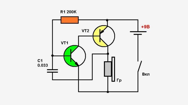
Simple DIY sound generator
Let's consider the simplest example - the howler monkey. You only need four elements: a film capacitor, 2 bipolar transistors and a resistor for adjustment. The load will be an electromagnetic emitter. A simple 9V battery is enough to power the device. The operation of the circuit is simple: the resistor sets the bias to the base of the transistor. Feedback occurs through the capacitor. The tuning resistor changes the frequency. The load must have high resistance.
With all the variety of types, sizes and designs of the considered elements, powerful transistors for ultra-high frequencies have not yet been invented. Therefore, generators based on self-oscillation transistors are used mainly for the low and high frequency ranges.
Video
Measurement technique
NE555 generator with frequency control
By the way, the NE555 microcontroller was developed back in 1971 and is so successful that it is used even today. There are many analogs, more functional models, modifications, etc., but the original chip is still relevant.
Description NE555
The microcircuit is an integrated timer. Currently produced primarily in DIP packages (previously there were round metal versions).
The functional diagram looks like this.

Rice. 1. Functional diagram
Can operate in one of two main modes:
1.Multivibrator (monostable);
2.Pulse generator.
We are only interested in the last option.
Simple generator on NE555
The simplest diagram is presented below.

Rice. 2. NE555 generator circuit

Rice. 3. Output voltage graph
Thus, the calculation of the oscillation frequency (with period t on the graph) will be performed based on the following formula:
f = 1 / (0.693*С*(R1 + 2*R2)),
Accordingly, the formula for the full period is:
t = 0.693*С*(R1 + 2*R2).
The pulse time (t1) is calculated as follows:
t1 = 0.693 * (R1 + R2) * C,
then the gap between pulses (t2) is like this:
t2 = 0.693 * R * 2 * C
By changing the values of the resistors and capacitor, you can obtain the required frequency with a given pulse duration and pause between them.
Adjustable frequency generator on NE555
The simplest option is to redesign the unregulated generator circuit.

Rice. 4. Generator circuit
Here the second resistor is replaced with two adjustable ones connected with back-to-back diodes.
Another option for an adjustable oscillator on a 555 timer.

Rice. 5. Circuit of an adjustable oscillator on a 555 timer
Here, by switching the switch position (by turning on the desired capacitor), you can change the adjustable frequency range:
- 3-153 Hz;
- 437-21000 Hz;
- 1.9-95 kHz.
The switch in front of diode D1 increases the duty cycle; it doesn’t even need to be used in the circuit (during its operation, the frequency range may change slightly).
It is best to mount the transistor on a heat sink (even a small one).
The duty cycle and frequency are controlled by variable resistors R3 and R2.
Another variation with regulation.

Rice. 6. Scheme regulated generator
IC1 is an NE555N timer.
The transistor is a high-voltage field-effect transistor (to minimize the heating effect even at high currents).
A slightly more complex circuit that works with a larger number of control ranges.

Rice. 7. Circuit operating with a large number of control ranges
All details are already indicated on the diagram. It is regulated by turning on one of the ranges (on capacitors C1-C5) and potentiometers P1 (responsible for frequency), P4 (responsible for amplitude).
The circuit requires bipolar power supply!
Publication date: 21.02.2018
Readers' opinions
- Valentin / 06.16.2019 - 18:53
Under Fig. 3 in the formula for the duration of the pause between pulses, remove the extra asterisk and bring the formula to the form t2=0.693×R2×C - shadi abusalim / 03.09.2018 - 13:55
Please help you use the electronic circuit using the built-in 555 To adjust the pulse width and control it, to add control to the flash, extinguish and light the lamp in the same circle The frequency of the circuit should be up to 500KHz There is a circle located on the site similar but mail fluctuates slightly [email protected] The current and frequency are controlled by the variable resistors R3 and R2. Another variation with regulation. Fig. 6. Scheme of the regulated generator


