Automatic systems for protecting electrical circuits, which replaced fuses, are widely used not only in extensive networks of industrial enterprises, but also in household electrical wiring. The machines are compact, reliable, and easy to operate. You can protect the electrical wiring of your home network using single-pole circuit breakers. But there are often cases when, in order to fully protect electrical installations, it is necessary to install a two-pole circuit breaker. Sometimes a complex electrical network can be protected solely with the help of group circuit breakers.
The peculiarity of multi-pole circuit breakers is that they disconnect several lines at the same time. This property is very useful in three-phase circuits, since disconnecting only one phase wire can lead to the failure of electric motors and other equipment. Similar problems in a two-wire circuit are solved using two-terminal networks.
Design and principle of operation
The design of a two-pole switch is identical to that of a single-pole circuit breaker. In other words, this device consists of two single-pole circuit breakers combined in one housing. Its peculiarity is that in these protective devices, in emergency situations, both protected lines are automatically switched off simultaneously. In principle, you can make a basic two-pole circuit breaker yourself by tightly connecting the control levers of two single-pole circuits with a bar.
Attention! It is impossible to replace a two-pole circuit breaker with two single switches operating separately! You should also not use single switches connected by a jumper as a two-pole circuit breaker. The design of the two-terminal device also contains a blocking mechanism, which is not present in the “improved” device from.
To understand the structure and operating principle of a two-pole circuit breaker, it is enough to understand the structure of a machine with one pole. The simplest such device consists of a bimetallic plate and the design of a charging and releasing mechanism. By the way, the outdated machines looked exactly like this. The design of such a switch is shown in Figure 1.
In situations equivalent to a short circuit or during prolonged overloads in single-phase circuits, the bimetallic plate heats up and, due to deformation, acts on the operating lever of the structure. The protective shutdown mechanism is triggered and the circuit is broken.
Figure 1. Old style circuit breaker
The operating principle of this device is very simple. When the rated currents exceed the permissible parameters, the thermal release actuates the moving contact and the circuit is broken. The power cut-off mechanism can operate in two cases - during an overload or due to a short circuit. To connect the power, it is necessary to eliminate the cause of the operation currents, and then turn on the machine by pressing the control lever.
The operating scheme is simple and reliable. However, it has a significant drawback: the machine does not respond to leakage currents, therefore it cannot protect against electric shock or prevent the wiring from catching fire in the event of sparking. Additional devices are required for complete protection.
Modern two-pole packages do not have this disadvantage. Figure 2 shows the design of such a circuit breaker. Its design has one important detail - an electromagnetic release. Such two-pole devices combine the functions of conventional and residual current devices (RCDs).
 Figure 2. The structure of a modern machine
 Thanks to the electromagnetic release, the charging and tripping mechanism of the two-pole circuit breaker reacts to leakage currents. This is the same blocking device discussed above.
Operating principle of an electromagnetic release.
Along a two-wire line, current flows in two opposite directions - along the phase conductor in one direction, and along the neutral conductor in the other. At the rated voltage, the magnetic fluxes in the solenoid coils, induced by equal counter currents, are compensated. Therefore, the resulting magnetic flux is zero.
But as soon as a leak appears, the balance is disrupted, and the resulting magnetic flux will pull the rod into the solenoid. He, in turn, will activate the levers of the cocking and release mechanism. A two-pole circuit breaker will open 2 poles, regardless of which conductor has a leak or short circuit. The RCD will trip as a reaction to changes in the parameters of the differential currents.
Purpose
In the case of a single-circuit electrical circuit, often used in the electrification of houses, it is not advisable to use two-pole circuit breakers to protect the network. This problem is successfully solved by single-pole switches, since there is no particular need to simultaneously disconnect different segments of the circuit. In single-phase wiring with a grounded neutral, when all neutral conductors are short-circuited to neutral buses, you can also get by with single switches.
A completely different situation arises in cases where some equipment cannot be connected to one common circuit. For example, if a transformer is used to power a group of electrical appliances, then you can’t do without a two-pole circuit breaker. The explanation is simple - there is no phase and zero at the output of the transformer. Cutting off the electric current on one of the wires does not exclude the presence of voltage on the other. Only the simultaneous disconnection of two poles ensures the safety of the equipment.
Installing a two-terminal network allows you to combine the tasks of differential protection and RCD in one device. In this case, it is no longer necessary to install separate discrete residual current devices.
Four-pole circuit breakers operating in three-phase networks using neutral wires operate on a similar principle. Three-phase loads are protected from short circuit.
By the way, the PUE does not prohibit the use of two-pole switches as input circuit breakers. They can also be used to protect group and individual loads. But, under no circumstances should ground wires be connected through this device. Remember that breaking the PE wire is only allowed when removing the plug from the socket.
Advantages and disadvantages
Two-pole circuit breakers provide control of lines with single-phase power supply, as well as protection of equipment operating in three-phase circuits.
The advantages of these devices include:
- reliable protection of homes, offices and industrial premises from network surges;
- the ability to control the power of individual electrical appliances and installations;
- ease of installation and maintenance. Two-pole AVs are ideal for branching and structuring wiring in the electrical supply of premises.
Of course, the main advantage is that a two-pole circuit breaker simultaneously de-energizes two conductors, regardless of which of them the accident occurred. This guarantees a complete absence of voltage in the protective conductors.
Disadvantages include:
- there is a possibility of cable breakdown when two loaded lines are turned on simultaneously;
- in rare cases, if the thermal release fails, an arbitrary power outage is possible even in the rated voltage mode;
- the need to select two-pole circuit breakers in accordance with the design parameters of the network. If the sensitivity of the switch is too high, it will often trip without good reason, and if the speed of reaction to an unusual situation is too low, the machine will not notice the network overload.
Thanks to the unique advantages, the use of two-pole switches is justified even taking into account the existing likelihood of the manifestation of these disadvantages.
Installation and connection diagrams
Mounting devices on a DIN rail is very simple. For this purpose, special grips (latches) are provided on the back side of the machine (Fig. 3). Connecting wires to the device terminal is also not difficult: the wires are easily clamped with bolts on the device terminals. By default, input wires are connected to the upper terminals, and output wires are connected to the lower terminals.
 Figure 3. Mounting the machines
 The generally accepted connection diagram is as follows:
- An input switch AB is installed in front of the meter.
- After the meter with a single-phase input, a two-pole AB is mounted.
- If a three-phase input is provided, then use a three-pole or four-pole circuit breaker, depending on the connection diagram of the neutral conductors.
In complex branched circuits, there can be several two-pole circuits, after which, one more single-pole automaton is installed on each branch. An example of such a circuit with a common zero bus is shown in Figure 4. Please note that a two-pole automaton was used for phase input. There are no other input devices in this diagram.
 Rice. 4. An example of a circuit diagram for switching on circuit breakers
 How to choose a two-terminal network?
In order for the circuit breaker to fully provide the necessary protection, it is necessary to carefully consider its choice. The main thing is not to make a mistake with. To do this, you need to know the rated load that you plan to connect to the device.
The current in the circuit protected by the machine is calculated using the formula: I = P/U where is the network voltage.
For example: if a 400 W refrigerator, a 1500 W electric kettle and two 100 W light bulbs are connected to the device, then P = 400 W + 1500 W + 2 × 100 = 2100 W. At a voltage of 220 V, the maximum current in the circuit will be equal to: I=2100/220= 9.55 A. The rating of the machine closest to this current is 10 A. But during the calculations, we did not yet take into account the wiring resistance, which depends on the type of wires and their cross-section. Therefore, we buy a switch with an operating current of 16 amperes.
We provide a table that helps determine the network power to be taken into account when calculating current strength.
| Current strength | 1 | 2 | 3 | 4 | 5 | 6 | 8 | 10 | 16 | 20 | 25 | 32 | 40 | 50 | 63 | 80 | 100 | |
| Single-phase network power | 02 | 04 | 07 | 09 | 1,1 | 1,3 | 1,7 | 2,2 | 3,5 | 4,4 | 5,5 | 7 | 8,8 | 11 | 13,9 | 17,6 | 22 | |
| Wire sizes | copper | 1 | 1 | 1 | 1 | 1 | 1 | 1,5 | 1,5 | 1,5 | 2,5 | 4 | 6 | 10 | 10 | 16 | 25 | 35 |
| aluminum | 2,5 | 2,5 | 2,5 | 2,5 | 2,5 | 2,5 | 2,5 | 2,5 | 2,5 | 4 | 6 | 10 | 16 | 16 | 25 | 35 | 50 | |
Using the table, you can accurately calculate the necessary parameters of a two-pole circuit breaker.
As for the stores where you can buy them, focus on prices and product range. From the list of manufacturers we can recommend, for example, the Legrand brand.
Video on the topic
The process of installing machines in an electrical panel is quite simple and does not take much time. The only problem is to do everything correctly, because when connecting wires, many novice electricians make small mistakes that can damage the device in a short period of time. In this article we will look at how to connect a circuit breaker with your own hands, providing installation rules, basic errors and diagrams.
Typical installation mistakes
Most often, when, and in particular connecting a machine, the following errors are made:
Another important point on which there is a lot of discussion is whether it is possible to connect the machine in front of the electricity meter or is this done only after it? The answer is that it is possible, and even necessary, the main thing is to buy a special box, which is sealed by energy sales representatives. Installing an input machine in front of the electric meter will allow you to safely replace the electricity control device both in a private house and in an apartment.
Here, in fact, are the rules for installing and connecting an electrical machine with your own hands. Now let's move on to the main topic of the article.
Main process
So, in the initial position we have an electrical panel in which the products will be installed, as well as all the wires (input and outgoing to consumers).

Let's look at the instructions for dummies using the example of connecting a two-pole circuit breaker in a panel:
- The first step is to turn off the power and check its presence using a multimeter or an indicator screwdriver. we provided to the readers!
- The machine is installed on a special mounting DIN rail and snapped into place with a latch. You can do without a DIN rail, but it is less convenient.
- The conductors of water and outgoing conductors are stripped to 8-10 mm.
- You need to connect the input zero and phase to the two upper terminals (do not forget about the recommendations indicated above).
- Accordingly, the outgoing zero and phase (those that go to electrical appliances, sockets and switches) are fixed in the two lower holes.
- After this, the place must be checked manually for reliability. To do this, you need to carefully take the conductor and move it in different directions. If the core remains in place, then the connection is reliable, otherwise be sure to tighten the screw again.
- After all electrical installations, the robot is supplied with voltage to the network and the functionality of the product is checked.
That's all the instructions for connecting a circuit breaker in a single-phase circuit. As you can see, there is nothing complicated, you just need to be careful. We also recommend watching the video tutorial, which discusses the connection process in more detail:
Visual video instructions
Installation of a low-quality single-pole circuit breaker
Connection diagrams


The video examines in more detail the connection diagrams for a single-pole, two-pole, three-pole and four-pole circuit breaker:
Overview of circuits
The comfortable living of all its inhabitants and the uninterrupted operation of household appliances depend on the correct connection of electrical wiring in the house. Do you agree? To protect the equipment in the house from the consequences of overvoltage or short circuit, and the inhabitants from the dangers associated with electric current, it is necessary to include protective devices in the circuit.
In this case, it is necessary to fulfill the main requirement - the connection of the RCD and circuit breakers in the panel must be done correctly. It is equally important not to make a mistake when choosing these devices. But don't worry, we'll tell you how to do it right.
This article will discuss the parameters by which RCDs are selected. In addition, here you will find features, rules for connecting machines and RCDs, as well as many useful connection diagrams. And the videos given in the material will help you put everything into practice, even without the involvement of specialists, if you have at least a little knowledge of electrical engineering.
To connect the RCD in the panel, two conductors are needed. Through the first of them, the current flows to the load, and through the second, it leaves the consumer along the external circuit.
As soon as current leakage occurs, a difference appears between its values at the input and output. When the result exceeds a predetermined value, it is triggered in emergency mode, thereby protecting the entire apartment line.
Residual current devices are negatively affected by short circuits (short circuits) and voltage surges, so they themselves need to be covered. The problem is solved by including automata in the circuit.
The RCD contains a ring-shaped core with two windings. The windings are identical in their electrical and physical characteristics
The current powering electrical appliances flows through one of the core windings in one direction. It has a different direction in the second winding after passing through them.
Independent installation of protection devices involves the use of diagrams. Both modular RCDs and machines for them are installed in the panel.
Before starting installation, you need to resolve the following issues:
- how many RCDs should be installed;
- where they should be in the diagram;
- how to connect so that the RCD works correctly.
The rule of electrical installation is that all connections must go into the connected devices from top to bottom.
Professional electricians explain this by saying that if you start them from below, the efficiency of the vast majority of machines will decrease by a quarter. In addition, the foreman working in the switchboard will not have to further understand the circuit.
RCDs designed for installation on separate lines and with low ratings cannot be installed in a general network. Failure to comply with this rule will increase both the likelihood of leaks and short circuits.
Selection of RCD according to main parameters
All technical nuances associated with the choice of RCDs are known only to professional installers. For this reason, specialists must select devices when developing a project.
Criterion #1. The nuances of selecting a device
When choosing a device, the main criterion is the rated current passing through it in long-term operating modes.

Based on the stable parameter - current leakage, there are two main classes of RCDs: “A” and “AC”. Devices of the latter category are more reliable
The value of In is in the range of 6-125 A. Differential current IΔn is the second most important characteristic. This is a fixed value, upon reaching which the RCD is triggered. When choosing it from the range: 10, 30, 100, 300, 500 mA, 1 A, safety requirements take priority.
Affects the choice and purpose of installation. To ensure the safe operation of one device, they are guided by the rated current value with a small margin. If protection is needed for the house as a whole or for an apartment, all loads are summed up.
Criterion #2. Existing types of RCDs
RCDs should also be distinguished by type. There are only two of them - electromechanical and electronic. The main working unit of the first is a magnetic circuit with a winding. Its action is to compare the values of the current going into the network and returning back.
There is such a function in the second type of device, but it is performed by an electronic board. It only works when there is voltage. Because of this, the electromechanical device protects better.

The electromechanical type device has a differential transformer + relay, and the electronic type RCD has an electronic board. This is the difference between them
In a situation where a consumer accidentally touches a phase wire and the board turns out to be de-energized, if an electronic RCD is installed, the person will come under voltage. In this case, the protective device will not work, but the electromechanical device will remain operational under such conditions.
The subtleties of choosing an RCD are described in.
Installation of RCDs and automatic machines in the panel
The electrical panel, in which the metering and load distribution devices are located, is usually the place for installing the RCD. Regardless of the chosen scheme, there are rules that are mandatory when connecting.
Main rules of connection
Along with the automatic shutdown device, they are also installed on the shield. All you need for this is a minimum of tools and a competent diagram.
The standard set should consist of:
- from a package of screwdrivers;
- pliers;
- side cutters;
- tester;
- socket wrenches;
- Cambric.
Also for installation you will need a VVG cable of different colors, selected in cross-section in accordance with the currents. The PVC insulating tube is used to mark the conductors.
When there is space on the DIN block available on the panel, a residual current device is mounted on it. Otherwise, install an additional one.
The key principle of installation is the following: contact of the neutral conductor after the RCD with either the input zero or grounding is unacceptable, therefore it is insulated in the same way as other conductors.
The circuit breaker must be switched on in series with the RCD. This is also one of the most important rules.
When the entire home is protected using one RCD, a circuit that includes several circuit breakers is used.

To eliminate the presence of additional wires on the shield, which does not look very aesthetically pleasing, a comb (distribution) bus is used to connect a bundle of wires
The project includes, in addition to additional AVs, one more component - a zero bus insulator. Mount it on the panel body or on a DIN rail.
This addition is introduced due to the fact that with a large number of neutral conductors connected to the output terminal of the disconnecting device, they simply will not fit in one clamp. An isolated zero bus is the best way out of this situation.
Sometimes electricians, in order to place the entire bundle of neutral wires in the socket, decide to cut the cores of a single-core cable. In the case where the cable is multi-core, several cores are removed.
It is better not to use this option, since due to a decrease in the cross-section of the conductors, the resistance will increase, and therefore the heating will increase.
Both the number of mounting holes and their diameter may vary. The ground bus is attached directly to the body.
Neutral wires in one twist are an additional inconvenience when identifying damage on the line, as well as when you need to dismantle one of the cables. Here you cannot do without unscrewing the clamp and unwinding the harness, which will certainly provoke the appearance of cracks in the veins.
You cannot install two wires simultaneously into one socket. The inputs of the circuit breakers are connected by jumpers. As the latter, during professional installation, special connecting tires called “comb” are used.
Features of connection diagrams
The choice of scheme involves taking into account the characteristics of a particular electrical network. Among the numerous options, there are only two circuits used to connect machines and RCDs in, which are considered the main ones.

The simplest installation diagram for automatic machines and protective devices. It can be used to connect from one to several loads connected in parallel
The first and simplest method, when one RCD protects the entire electrical network, has disadvantages. The main one is the difficulty in identifying the specific location of the damage.
The second is that when some kind of failure occurs in the functioning of the RCD, the entire system will be taken out of operation. The residual current device is allocated a place immediately after the meter.
The next method provides for the presence of such devices on each individual line. If one of them fails, all the others will be in working order. To implement this scheme, a larger shield and greater financial costs are required.
Details about a simple scheme
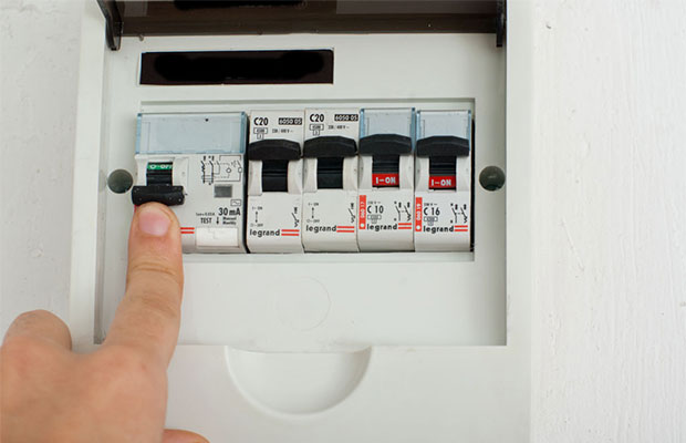
Let's consider connecting an RCD with automatic circuit breakers to a simple residential switchboard. At the entrance there is a two-pole automatic switch. A two-pole RCD is connected to it, to which there are two single-pole circuit breakers.

There is a “Test” button on the RCD body. It is intended to test its operation. Manufacturers advise using this key at least once a month and checking the operation of the device itself.
The phase supplied to the circuit breaker enters the input of the RCD with output to the circuit breakers. The zero output from the machine goes to the zero bus, and from it to the input to the device.
From its output, the neutral conductor is directed to the second neutral bus. The presence of this second bus is a special nuance, without knowing which it is impossible to achieve the normal functioning of the circuit.
The RCD in the process of operation controls both the incoming and outgoing voltage - how much has entered at the input, so much should be at the output.
If the equilibrium is disturbed and at the output it is greater than the setting value to which the RCD is configured, it trips and automatically turns off the power. The zero bus is responsible for this process.
In electrical circuits where the installation of a residual current device is not provided, there is only one common zero.
In circuits with RCDs the picture is different - several such zeros are already present here. When using one device, there are two of them - a common one and one with respect to which the protective device operates.
If two RCDs are connected, there are three zero buses. They are designated by indices: N1, N2, N3, etc. In general, there are always one more zeros than residual current devices. One of them is the main one, and all the others are tied directly to the RCD.

Color designation of electrical wires according to the rules established by the PUE. This marking must be studied before proceeding with the installation of protective devices.
If not all equipment is supposed to be connected through the RCD, then zero is supplied from the common bus. In this case, the residual current device is removed from the circuit.
When adding a single-pole circuit breaker operating from an RCD, the phase from the output of the latter is supplied to the input of the circuit breaker. From the output of the switch, the conductor is connected to one load contact. Zero on it is brought to the second conclusion. It comes from the zero bus created by the RCD.
There is one more element on the shield - a protective grounding bus. Correct operation of the RCD without it is impossible.
Three-wire network is only available in new houses. It must have a zero phase and grounding. In houses built a long time ago, there is only a phase and a zero. In such conditions, the RCD will also function, but slightly differently than in a three-phase network.
As a way out, the grounding is carried out by a third conductor to the sockets, and then to the ceiling to the place where the chandeliers are connected. Ground is not supplied to the switches.
Option for connecting machines without RCD
There are times when one of the machines needs to be connected without bypassing the residual current device. Power is connected not from the output of the RCD, but from the input to it, i.e. directly from the machine. The phase is supplied to the input, and from the output it is connected to the left terminal of the load.
Zero is taken from the common zero bus (N). If a fault occurs in the area controlled by the RCD, it will be removed from the circuit, and the second load will not be de-energized.
RCD in a three-phase network
A network of this type includes either a special three-phase RCD with eight contacts, or three single-phase ones.

Place the RCD connection diagram on its body. Wires coming from the output terminals lead to the apartment's distribution network
The connection principle is completely identical. Mount it according to the diagram. Phases A, B and C supply power to loads rated at 380 V. If we consider each phase separately, then in tandem with cable N (0), it provides a series of single-phase 220 V consumers.
Manufacturers produce three-phase trip protection devices adapted to high leakage currents. They only protect electrical wiring from fire.

The photo shows two diagrams: a trip protection device in a single-phase and three-phase network of the TN-C-S system. This means that the neutral cable is divided into working and protective
In order to protect people from the effects of electric current, single-phase two-pole RCDs are installed on the outgoing branches, configured for leakage current in the range of 10-30 mA. For cover, a machine gun is placed in front of everyone. In the circuit after the RCD, the working zero and ground cannot be connected.
RCDs and circuit breakers on a three-phase switchboard
Let us examine in detail a not entirely standard circuit assembled on a three-phase distribution panel.
It contains:
- three-phase input circuit breakers - 3 pcs.;
- three-phase residual current device - 1 pc.;
- single-phase RCDs - 2 pcs.;
- single-pole single-phase circuit breakers - 4 pcs.
From the first input circuit breaker, voltage is supplied to the second three-phase circuit breaker through the upper terminals. From here, one phase goes to the first single-phase RCD, and the second to the next.

The voltage from the second input circuit breaker is supplied to a three-phase RCD, the lower terminals of which are connected to a three-phase load. This protective device protects against leakage currents, and the second input circuit breaker protects against short circuits.
Single-phase RCDs installed on the panel are two-pole, and automatic machines are single-pole. For the protective device to function correctly, it is necessary that the working zeros after it are not connected anywhere else. Therefore, after each RCD, a zero bus is installed here.
When the machines are not one-pole, but two-pole, then there is no need to install a separate zero bus. If two zero buses are combined, false positives will occur.
Each of the single-pole RCDs is designed for two circuit breakers (1-3, 2-4). A load is connected to the lower terminals of the machines.
The common ground bus is installed separately. Three phases enter the input circuit breaker: L1, L2, L3, the working neutral wire N and PE - protective.
The zero is connected to the common zero, and from it goes to all the RCDs. Then it goes to the load: from the first device - to three-phase, and from the next single-phase - each to its own bus.

In a three-phase network, electrical quantities are vector, therefore their total value is determined not by the algebraic, but by the vector sum of these quantities
Although this distribution panel has a three-phase input, the wire is not divided into PEN and PE, because five-wire input. Three phases, zero and grounding come to the shield.
Conclusions and useful video on the topic
Nuances of installing all elements:
RCD installation details:
RCDs and automatic devices are technically complex equipment. It is advisable to install it in places where electric current can pose a threat to both the safety of people and home appliances.
Its installation requires taking into account many parameters, so both calculation and installation are best performed by qualified specialists.
If you have experience in installing RCDs yourself, please share it with our readers. Tell us what points you should pay special attention to. Leave your comments and ask questions in the block below the article.
And choosing the right protection, you need to connect it correctly. At first glance, there are no difficulties in this. The procedure is quite simple: we strip the cable, insert it into the terminals and tighten the screws. But, as practice shows, many inexperienced users make a number of serious mistakes when doing this.
And so, let's look at the main points of correctly connecting a circuit breaker to a distribution board and look at the most common mistakes.
How to connect the phase correctly - from above or below?
Each AB is equipped with moving and fixed contacts. On many thematic forums, disputes often arise about which of them should be connected to power? If we refer to the 7th edition of the Electrical Installation Rules (ELR), then according to paragraph 3.1.6 the phase must be connected to a fixed contact. But, there are exceptions to any rule. And so, let's look at where the fixed contact is installed in single-pole switches.
The naked eye can see that the upper clamp made by IEK is stationary. The indicators on the case confirm this.

Such designations are also used by other manufacturers, for example, fixed contacts are installed on top, and moving contacts are installed on the bottom.


In the models reviewed above, the fixed connection is on top(as in old Soviet-made models). But how to determine its location in Chinese models without markings on the body?!
According to the rules of the PUE, switching the power wire from above is a requirement of aesthetics and order. In the same way, industrial switches of the Republic of Belarus are connected from above - when disconnected, the electrician will know for sure that the lower connection is de-energized.
But, as practice shows, the phase can also be connected from below and even from the side, depending on wiring planning. As a rule, the better the installation of modular equipment, the faster and easier it is to determine the direction of current movement, regardless of the location of the phase entry.
Incorrect connection of a single-core cable to the machine
Let's look at the most common mistakes made when connecting.
The first mistake is the insulation clamp in the connection

Quite often, inexperienced users clamp the edge of the insulation into the terminal along with the conductor, which can melt.
In the best case, this error will manifest itself in the burnout of the machine and the loss of power to the room; in the worst case, it can cause a fire.


The second error is switching cores with different cross-sections in one terminal
To connect several machines to the power line it is better. If you don’t have it at hand, you can make a jumper yourself from a conductor core.


Making a jumper is quite simple: we take a solid piece of wire and, without removing the insulation, form a jumper of a suitable size.


Electricians not recommended connect machines with jumpers made of cables of different cross-sections, since when clamping, only a conductor with a large cross-section is well tightened; a smaller conductor with poor contact can melt the housing and lead to a fire.


Example: a conductor with a cross-section of 4 mm² was connected to the first switch, and 2.5 mm² to the others. The photo clearly shows how, due to a poor connection, the temperature of the smaller conductor increased, which melted the insulation and casing.

For clarity, let's try to connect two wires with a diameter of 2.5 mm² and 1.5 mm². No matter how strong the clamp is, the wire with a smaller cross-section rotates freely in the terminal.


In the photo of wires with different cross-sections in a difavtomat - the smaller one sparks and melts the insulation.

In expensive series from large manufacturers, such as the problem of connecting wires with different cross-sections, the problem was solved with the help of special clamps that compress them and hold them firmly in connection with the contact. Or Hager, which use Bi-Connect technology.
For greater connection strength, notches are made on the walls of the clamps, which can sometimes be found even in cheap analogues. Connecting a multi-core cable without a ferrule is also allowed, only after a certain time you need to tighten the clamping screws.
Third mistake - terminating cable cores


10 mm of insulation is removed from the end of the wire, the bare part is inserted into the contact and tightened with a screw - this is how electricians most often make the connection.
As a result, the contact holds well, but its strength can be improved by simply making a U-bend at the end.


This increases the area of contact between the conductor and the clamp, which increases the reliability of the connection.

Connecting multi-core cables to AB
During installation, a soft multi-core cable is most often used - it is easier to install than a single-core cable, but there are also some peculiarities when connecting it.
One of the most common mistakes is crimping a wire without termination, in which thin wires break off and fall off due to squeezing. The cable begins to lose cross-sectional area, which causes the contact strength to deteriorate, which can lead to already known consequences.


Before connecting to a connection, the stranded wire must be terminated using.

For fastening two wires in one clamp a special tip NGI-2 is used, which also makes it possible to form jumpers for group connection of several circuit breakers.
Is it possible to solder the wire under the clamp?

Some users, in order to save money and because they do not want to spend money on lugs and other “installation details,” terminate conductors by soldering.


What dangers can such a connection pose?


Over time, under the influence of temperature from the passing current, the solder begins to melt. There is a need to regularly check the strength of the connection and tighten the clamp. In practice, no one pays attention to this. The conductor heats up more and more, and the connection weakens, as a result, the contact burns out, which can cause a fire.
Using a comb tire or why “invent a bicycle”?

Fortunately, there is an excellent analogue that replaces jumpers - a comb. Its use has a number of advantages:
- Easy installation;
- More reliable contact connections;
- Safety in operation, since conductive parts are completely insulated;
- Versatility, because you can always cut the tire to the desired length;
- Convenient distribution of modular devices into groups;

During installation, this is not only an excellent practical solution, but also an aesthetic factor. If the network is expanded and other devices are installed, dismantling the jumpers will cause a lot of difficulties, but not the combs, which can be quickly and safely removed and then reinstalled. For reliable and durable fixation, two types of combs are used:
The pin type is more convenient for installation than the U-shaped one, but its connection is less durable. The second has a larger connection area, which is placed around the lag screw, which makes the contact almost impossible to pull out, even with force.

Due to the fact that some cases are equipped with clamps for a certain type of bus, almost every electrician always has both of them with him.

As a rule, premium series have clamps for both types of tires at the same time.
Dividing machines into groups

Modular devices in a cabinet are usually divided into several groups according to the selectivity of power supply. The simplest example is to separate the outlet line and lighting. In addition, there can be several outlet lines - for rooms, kitchen, bathroom, etc. As a rule, a separate group is separated by a comb, where a phase is supplied to one of the devices.

From the point of view of safety and aesthetics, plugs are placed on the sides of the bus to cover the contacts with insulation, which is convenient if two groups are very close. The rule of good form is to use it in shields. They perform three important functions:
- Division into groups for ease of work;
- Providing heat removal;
- Strong fixation of housings.
When a large number of machines with supplied current are placed closely together, they heat up. And since the space between them is minimal, air does not circulate and the temperature rises, which changes the characteristics of thermal releases.
Movable latches - for ease of installation

Depending on the prospects for expanding the network, which will entail an increase in the number of machines, it is worth paying attention to their fastenings, which can be fixed using one or two movable latches.
Why are two latches better? It may seem to many inexperienced users that there is no difference in the method of attaching the module, but the first time you replace the machine everything will become clear - to remove the device with one movable latch will require complete disassembly of the entire shield. This problem can be avoided if you purchase an AB with two movable latches.
For example, they are in, the removal of which takes a couple of minutes using a screwdriver, unlike other types of fastenings, the dismantling of which will take a lot of time and nerves.
If you are faced with a choice, our qualified managers are always ready to help.
An ordinary person is unlikely to know how to connect a circuit breaker. After reading this article, you will learn what machines are needed for, how to determine exactly where they are located and what to do if they work.
Circuit breaker - why is it needed?
The purpose of the machines is to switch electrical circuits, that is, to turn them off and on if necessary. Having carefully examined this device, you will notice a small lever with which the apartment owner can turn off or turn on the electrical circuit. However, the name contains the word “automatic”, which hints to us that the operation is automatic.
This happens in one of two cases:
- The flow of current through the circuit exceeds the permissible limits. The shutdown may not occur immediately, but the higher the value, the faster the device will turn off the electrical circuit.
- In case of short circuit. Then the operation occurs instantly, within a few fractions of a second.
Each person who is going to connect electrical circuit breakers in a panel with his own hands must be as careful and attentive as possible when working, avoid contact with exposed wires and follow all electrical and fire safety rules.
Buying vending machines - what you should pay attention to
A correctly selected device is the key to reliable operation of all electrical appliances in your apartment, so you need to approach your choice responsibly. Ideally, seek help from an electrician who will tell you which model is suitable in your case. If such an opportunity did not arise, then the next chapter is especially for you.
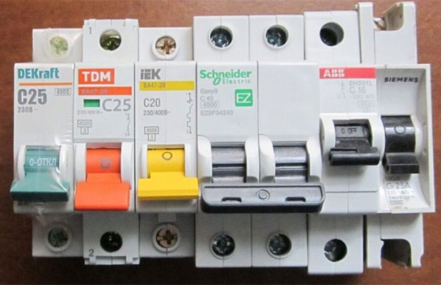
So, all the characteristics that matter when choosing a device are indicated on the product label. First, pay attention to the brand, which is usually located at the top of the machine panel. There is no need to save money when purchasing; give your preference to proven brands, for example, EKF, IEK, Schneider Electric, Merlin Green, Hager, Legrand, ABB. These manufacturers produce high-quality products that are distinguished by excellent performance characteristics, as well as reliability and long service life.
Frequency and voltage rating are another important consideration. In most cases, the inscription “220/400V/50Hz” is found, which means that the device is designed to operate with a current of 50 Hz in single-phase and three-phase circuits. This is the best option for any apartment owner, as it is ideal for providing reliable protection for all modern appliances and devices.
One of the most important parameters is the rated current. It indicates the maximum value of current in amperes that flows through the circuit breaker for a very long time without turning it off. If the rated current value is exceeded, the thermal release is activated, which disconnects the machine from the network. The greater the excess, the sooner the device will operate. It should be remembered that the rated current is selected in accordance with the cross-section of the wire or cable, but not the load power. In this case, the switch prevents the wires from overheating during the flow of electric current.
Another significant factor is the number of poles. In private houses and modern apartments, switches with a number of poles from one to four are used. Single-pole and double-pole devices are used in single-phase circuits, the rest are used to protect three-phase circuits. The number of modules, or places for machines, fully corresponds to the number of poles. There are 17.5 mm per module.

To avoid problems with how to properly connect circuit breakers in an electrical panel, you need to follow two simple rules:
- The rating of the machine should be determined based on the cross-section of wires and cables, but not the load.
- The cable cross-section corresponds to the maximum load when the devices are connected to the electrical network.
Connection tools - what we need
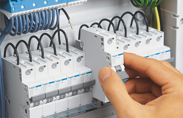
Installing circuit breakers is a rather complicated process, but with due care, anyone can perform all the operations. Opening the switchboard, you see that the electrical equipment is attached to a special DIN rail using a special latch. The width of this rail is 35 mm.

- Indicator screwdriver
- Stripper - a special tool used when stripping insulation
- Cable cutter or regular wire cutters
- Pliers of various sizes
- Phillips and slotted screwdriver set
- Crimper is a device for crimping ferrules when working with stranded wires.
Connection process - do it yourself
We have all the necessary tools at hand, and a device that corresponds to the parameters of the electrical circuit has also already been purchased. All that remains is to find out how to properly connect the machine in the electrical panel. First of all, it is necessary to completely de-energize the electrical panel, and also take measures to prevent the voltage from suddenly turning on. To make sure there is no mains voltage, use an indicator screwdriver.
The process of installing the machine itself is very simple; you just need to snap the device into any free space on the DIN rail. If there are empty spaces for new modules on the left or right, you should use a limiter, the task of which is to ensure that the static counter remains stationary. The following order is slightly different, depending on the number of poles:
- If a single-pole switch is connected, the phase of the protected circuit must go from the lower terminal, and the phase of the RCD or input device must go to the upper terminal.
- Two-pole circuit breakers are not much different, since similar phases are supplied to the upper and lower left terminals, while zero is supplied to the right terminals and, accordingly, also zero is removed.
- Three-pole switch - the upper phases are supplied based on their order, from left to right - A, B, C (L1, L2, L3). The phases leave in a similar order from the bottom of the device.
- A four-pole device is practically no different from a three-pole device. Only one right terminal is added at the top and bottom, which serve for zero pass.
It should be remembered that only incoming wires are attached to the upper terminals, while outgoing ones are installed on the lower ones. When laying wires, it is necessary to avoid sharp turns. This is due to the fact that in the future, creases may appear, causing power failures. After laying the wires, the length required for normal free entry into the terminal is measured, and the excess part is removed using wire cutters.
A prerequisite is compliance with all safety regulations! Electricity is no joke; it’s better to be on the safe side than to end up in a hospital bed.
Now a stripper is used, with which we remove 10 mm of insulating material from the end of the cable. When working with ordinary wires, you can proceed to the next step, but if you purchased multi-core cables, you will definitely need to terminate their ends using a crimper. If you do not have this tool, then working with stranded wires is strictly prohibited.
Having completed all the basic steps, it is recommended to once again check that the circuit breaker is connected correctly and whether the result of your efforts corresponds to the circuit diagram of this panel. Next, you need to place the cables in the terminals of the machines and clamp them with a screwdriver. It is not recommended to tighten it all the way as hard as possible, as this may damage the body of the device.
All that remains is to apply voltage, turn on all protective devices and check the voltage at the output and input of the machine using an indicator screwdriver. At this point the installation can be considered complete. Outwardly, everything seems quite simple and very fast, but in reality it will take a lot of time and effort to achieve the desired result, especially if you did not know how to connect the machine in the panel and are doing it for the first time.
The switch has tripped - what to do?
There are some important points to note when operating the machines. For example, what to do if the device suddenly works and cuts off the power supply. It is necessary to find out the cause of the problem and, if possible, eliminate its source. Although most people are in a hurry to immediately turn on the device again, which is fundamentally wrong. If only because when turned off, severe overheating of the internal components occurs, especially the solenoid and the bimetallic plate of the thermal release. You should wait about ten minutes for the device to return to normal operating temperatures, after which you can try turning it on.
During these ten minutes, you can walk around the house or apartment in order to detect faults. You need to carefully inspect all household appliances connected to the network, as well as sockets. Hot plugs, darkening from exposure to fire, and the appearance of a characteristic burnt smell indicate the source of the circuit breaker shutdown.
If there are several machines, you need to turn them on sequentially to localize the problem area. Thus, problems such as turning off the input machine may appear, which makes it possible to identify a specific electrical circuit. In this case, you should find the device that led to the short circuit, which may be a burnt-out lamp with a shorted filament or melted insulation.
The procedure is simple: turn off the machine and disconnect from the network all devices that consume energy from this network, then turn on the switch. If it works, then the problem is definitely in one of the household appliances. Otherwise, there are violations in the wiring or connection diagram, then it is recommended to call an electrician, since it will be very difficult to correct the situation on your own.
The most common cause of operation is the simultaneous activation of a large number of devices or the connection to the network of equipment that consumes too much electricity. For example, an air conditioner, washing machine, oven or powerful heater are turned on at the same time. Naturally, the machine is not able to cope with the multiple increased load, which results in its shutdown. The solution to the problem is as simple as possible - turn off some devices to reduce the load on the network.
Problems may occur in hot summer weather. The reason for this is the additional effect of thermal energy on the device, which can lead to shutdown. As practice shows, such phenomena occur only with old devices, while modern devices are practically immune to external weather conditions. This once again brings us back to the fact that you need to buy only high-quality machines from the best manufacturers.


