Modern engineers regularly conduct experiments to create devices with unconventional and non-standard designs, such as, for example, a rotation apparatus on. Among these mechanisms, it is worth noting the solenoid motor, which converts the energy of electric current into mechanical energy. Solenoid motors can consist of one or more coils - solenoids.
In the first case, only one coil is involved, when turning it on and off, mechanical movement of the crank mechanism occurs. The second option uses several coils that are switched on alternately using valves when current is supplied from the power source during one of the half-cycles of the sinusoidal voltage. The reciprocating motion of the cores drives the wheel or crankshaft.
Solenoid motor working principle
According to the basic classification, solenoid motors are resonant and non-resonant. In turn, there are single-coil and multi-coil designs of non-resonant motors. Parametric motors are also known in which the core is pulled into the solenoid, but takes the desired position when magnetic equilibrium is achieved after several oscillations. When the network frequency coincides with the natural vibrations of the core, resonance can occur.
Solenoid motors are compact and simple in design. Among the disadvantages, it should be noted the low efficiency of these devices and the high speed of movement. To date, these shortcomings have not been overcome, so these mechanisms have not been widely used in practice.
The operating coil of single-coil devices is turned on and off using a mechanical switch, due to the action of the core body, or a semiconductor valve. In both options, the reverse motion is ensured by a spring with elasticity. In engines with several coils, the working elements are turned on only by valves, when current is supplied to each coil in turn during one of the half-cycles of the sinusoidal voltage. The coil cores begin to retract one by one, as a result, this leads to reciprocating movements. These movements are transmitted through drives to various motors that perform the function of actuators.
Solenoid motor design
There are various types of mechanical and electrical devices whose operation is based on the conversion of one type of energy into another. Their main types are widely used in all machines and mechanisms used in production and at home. There are also non-traditional devices, work on which is still carried out at the experimental level. These include solenoid motors that operate on the basis of the magnetic action of current. Its main advantage is the simplicity of design and availability of materials for manufacturing.

The main element of this device is a coil through which electric current is passed. This leads to the formation of a magnetic field, which draws in a plunger made in the form of a steel core. Next, with the help of a crank mechanism, the translational movements of the core are converted into rotational movement of the shaft. You can use any number of coils, however, the most optimal option is considered to be one with two elements. All these factors must be taken into account when deciding how to make a solenoid motor with your own hands from scrap materials.
An option with three coils, which has a more complex design, is often considered. However, it has more power and runs much smoother without requiring a flywheel for smooth operation.

The operation of this device is as follows.
- From the electrical network, the current enters the distributor through the solenoid brush, after which it enters directly into this solenoid.
- After passing through the winding, the current returns to the network through common rings and a brush installed in the distributor. The passage of current leads to the formation of a strong magnetic field, drawing the plunger inside the coil towards its middle.
- Next, the translational movement of the plunger is transmitted to the connecting rod and crank, which rotate the crankshaft. Simultaneously with the shaft, the current distributor rotates, activating the next solenoid.
- The second solenoid begins to operate even before the end of the first element. Thus, it assists in weakening the thrust of the plunger of the first solenoid, since the length of its arm decreases during the rotation of the crank.
- After the second solenoid, the next - third coil - is switched on and the whole cycle is completely repeated.
DIY solenoid motor
The best material for reels is considered to be textolite or hardwood. For winding, PEL-1 wire with a diameter of 0.2-0.3 mm is used. Winding is carried out in an amount of 8-10 thousand turns, ensuring the resistance of each coil is within 200-400 Ohms. After winding every 500 turns, thin paper spacers are made, and so on until the frame is completely filled.

Mild steel is used to make the plunger. Cranks can be made from bicycle spokes. The upper head must be made in the form of a small ring-shaped ear with the required internal diameter. The lower head is equipped with a special grip for mounting on the crankshaft journal. It is made of two tin strips and is a fork that fits onto the crank neck. The final fastening of the plug is carried out with copper wire threaded through the holes. The connecting rod fork is put on a bushing made of copper, bronze or brass tube.
The crankshaft is made of a metal rod. Its cranks are located at an angle of 120 degrees relative to each other. A power distributor is mounted on one side of the crankshaft, and on the other, a flywheel in the form of a pulley with a groove for the drive belt.

To make a current distributor, you can use a brass ring or a piece of tube of suitable diameter. It turns out one whole ring and three half rings, located in relation to each other with a shift of 120 degrees. Brushes are made from spring plates or slightly riveted steel wire.
The current distributor bushing is mounted on a textolite roller, placed on one of the ends of the crankshaft. All fastenings are carried out using BF glue and dowels made from thin wire or needles. The distributor is installed in such a way that the first coil is turned on when the plunger is in the lowest position. If the wires going from the coils to the brushes are swapped, the shaft will rotate in the opposite direction.

The coils are installed in a vertical position. They are secured in different ways, for example, with wooden planks, which have recesses for the coil housings. Side panels made of plywood or sheet metal are attached to the edges, which provide space for installing bearings under the crankshaft or brass bushings. If there are metal sidewalls, the bushings or bearings are secured by soldering. It is recommended to install bearings in the middle part of the crankshaft. For this purpose, special tin or wooden racks are provided.
To avoid the crankshaft shifting in one direction or another, it is recommended to solder copper wire rings to its ends at a distance of approximately 0.5 mm from the bearings. The engine itself must be protected by a tin or plywood casing. Engine calculations are performed based on alternating electric current, voltage 220 volts. If necessary, the device can operate with direct current. If the mains voltage is only 127 volts, the number of turns of the coil should be reduced by 4-5 thousand turns, and the wire cross-section should be reduced to 0.4 mm. If assembled correctly, the power of the solenoid motor will average 30-50 W.
How to make a solenoid motor at home
The invention relates to power engineering and electrical engineering, namely to devices using the energy of permanent and electromagnets. It can be used as a drive with a wide power range for environmentally friendly engines and electric generators.
The objective of the invention is to create a simpler design of an electromagnetic motor that has better traction characteristics. The proposed design should provide more efficient conversion of the magnetic field of permanent and electromagnets into motion energy. Another task is to expand the arsenal of environmentally friendly technical means.
This task is achieved by the fact that the electromagnetic motor contains at least one movable and one fixed coaxial magnetic elements, interacting with their magnetic fields predominantly along their surfaces with acceleration in the direction of movement of the movable element in the trajectory section.
Such a magnetic motor according to the invention is characterized in that the interacting magnetic elements are made coaxial, which greatly increases the area of interaction between the moving and stationary magnetic elements. Coaxial magnetic elements also have a greater density of magnetic field interaction than flat plate magnets, which are dispersed unlike coaxial ones.
The magnetic elements of one of the groups are installed in a circle and are connected to an axis of rotation coinciding with the axis of the circle of installation of the other group of elements, and both circles coincide, and one group of magnetic elements has longitudinal slots in the internal radial direction, and the width of the slots is sufficient for the passage of the axial connection elements another group of magnetic elements.
In this case, the axial connection element of one of the groups of magnetic elements can be made in the form of a disk.
 Alternatively, the axial connection elements of one of the groups of magnetic elements are made in the form of spokes or plates.
In a specific embodiment, the magnetic motor contains a movable element, for example, in the form of a surface capable of rotating in a circle, on which n-magnetic elements are fixed, which are installed with the ability to interact with m-magnetic elements installed motionlessly. If each of the magnetic elements included in group m is made in the form of a permanent magnet, then the magnetic elements of group n are made in the form of an electromagnet. One of the groups of magnetic elements (m or n) consists of magnetic elements, each of which is made with a through channel connecting the ends of this magnetic element and a flat slot connecting the outer surface of the magnetic element with a through channel along its entire length. Another group of magnetic elements includes magnetic elements, each of which is installed in such a way that it is able to pass through the through channel of a magnetic element from another group. The magnetic elements of one of the groups are electromagnets, the turns of which are laid in such a way as not to overlap the flat slot connecting the entire length of the through channel with the outer surface of the magnetic element.
In the case when the magnetic elements of one of the groups are external elements of interacting coaxial magnetic elements and are an electromagnet, then their turns are laid in such a way as not to overlap the flat slot connecting the entire length of the through channel with the outer surface of the magnetic element. And the internal elements are permanent magnets from another group, interacting coaxial elements and represent a slightly curved rod, the shape of which is best described as a part of the body having a toroidal surface.
 In another case, when the magnetic elements of one of the groups are external elements of interacting coaxial magnetic elements and are permanent magnets, then each of them has a through channel connecting the ends of this magnetic element and a flat target connecting the outer surface of the magnetic element with the through channel along its entire length. And the internal magnetic elements are electromagnets, from another group of interacting coaxial magnetic elements and represent a slightly curved rod, the shape of which is best described as a part of the body having a toroidal surface.
We will show the operating principle of the proposed engine in two versions. In one embodiment, one of the groups of magnetic elements, which are stationary electromagnets, is rigidly attached to the motor housing. Another group of magnetic elements is fixed to the electric motor rotor using holders. Movable magnetic elements are permanent magnets that can freely pass through the through channels of fixed electromagnets. In the initial stage of operation of the electric motor, electric current is supplied to stationary electromagnets. An electromagnetic field appears in electromagnets, which draws moving permanent magnets into its cavity. Moving permanent magnets, which are accelerated due to the interaction of magnetic fields at the entrance to the channels of electromagnets, continue to move along the channel and approach the output hole of the electromagnet. The polarity of this part of the electromagnet coincides with the polarity of the approaching part of the moving permanent magnet. However, sharp braking of the moving permanent magnet does not occur, since at this time an electric current of the opposite polarity is automatically supplied to the electromagnets using an electronic or mechanical switch. As a result, the moving permanent magnet continues to move having received additional acceleration and leaves the cavity of the electromagnet and approaches the next stationary electromagnet located on the circle. As you approach the next electromagnet, their interacting magnetic fields of the same polarity also approach, and at this time a subsequent change in the polarity of the stationary electromagnet occurs. And the moving permanent magnet continues its movement. The described process can be continuously repeated not only for one permanent magnet and electromagnet, but for several other moving and stationary magnets.
Magnetic elements can be made both in the form of permanent magnets and in the form of electromagnets or their combinations, mounted on a ring or on another rotor.
Another design option for the electric motor is given below.
The present invention is illustrated by the accompanying graphic materials:
In fig. 1 shows an electromagnetic motor in the version where the fixed magnets are electromagnets, and the moving magnets are permanent magnets.
In fig. 2 – longitudinal section A-A of an electromagnetic motor with a four-rotor design.
In fig. 3 – cross section of the V-V electromagnetic motor.
In fig. 4 and fig. 5 options for an electromagnetic motor with a larger interaction area between magnetic elements (interacting magnetic elements of an elongated shape).
In fig. 6 electromagnetic motor in the version where the fixed magnets are permanent magnets, and the moving magnets are electromagnets.
 In another embodiment, the proposed magnetic motor relates to one of the examples of the preferred implementation of the invention. It consists of a housing 1 (Fig. 2, Fig. 3 and Fig. 6) and a housing cover 9 stationary permanent magnets 2 with a flat slot, rigidly mounted on the housing 1. Movable electromagnets 3 are rigidly mounted on the rotor 5 using holders 4. Rotor 5 is rigidly mounted on shaft 6 with the possibility of rotation together with shaft 6. Housing 1, housing cover 9, holder 4 and shaft 6 are made of a material that does not interact with magnets. A fixed permanent magnet 2 is a part of a toroidal body with a through channel connecting the ends of this body and a hollow slot connecting the outer surface with a through channel along the entire length of this body.
The movable electromagnet 3 is a slightly curved rod, the shape of which is best described as part of a body having a toroidal surface. The ends of the coils 7 of the electromagnets 3 are fixed to the current collection elements 8 and are powered electrically by means of the sliding plates of the switch (the switch-distributor is not shown). The switch-distributor changes the polarity of the supplied electric current depending on the location of the electromagnet 3 relative to the stationary permanent magnet 2.
The proposed engine works as follows. As shown in FIG. 6, electromagnets 3 fixed in holders 4 on a rotating rotor 5 can pass through the channels of fixed permanent magnets 2. When an electric current is supplied to the current collection elements 8 through a switch in the electromagnets 3, the ends of the coils 7, which are fixed to the current collectors 8, an electromagnetic field is excited. Electromagnet 3 is drawn into the through channel of permanent magnet 2, since the polarity of the poles of electromagnet 3 and permanent magnet 2 at the moment they approach each other is opposite. Electromagnet 3, which is accelerated by the interaction of magnetic fields at the entrance to the channel, continues to move and approaches another part of the output hole of the permanent magnet channel. However, sudden braking of electromagnet 3 does not occur. Structurally, it is ensured that the condition is met in which an electric current of opposite polarity is automatically supplied to the electromagnets 3 using an electronic or mechanical switch. As a result, the permanent magnet 2 pushes the electromagnet 3 out of its cavity as the polarity of the electromagnet 3 changes to the opposite, the interacting magnetic fields of the electromagnet 3 and the permanent magnet 2 in this area are the same. Subsequent movement of the electromagnet 3 together with the rotor 5 and shaft 6 ensures that the electromagnet 3 approaches the next permanent magnet 2 located around the circle. As the interacting like poles of electromagnet 3 and permanent magnet 2 approach, the next change in the polarity of electromagnet 3 occurs. And electromagnet 3 continues its movement. The described process is continuously repeated not only for the described electromagnet 3, but also for each electromagnet from among those fixed in the same way on the rotor 5.
Thus, it is possible to design the proposed motor with elongated shapes of interacting magnetic elements (Fig. 4), which increases their interaction area. Which means an increase in electric motor power.
It should be borne in mind that possible changes and modifications of the present invention will become apparent to one skilled in the art.
Another area of use of the proposed invention is the possibility of using it in the form of structures, each section of which includes its own rotor with fixed magnetic elements that interact with fixed magnetic elements.
Almost everything in our lives depends on electricity, but there are certain technologies that allow you to get rid of local wired energy. We propose to consider how to make a magnetic motor with your own hands, its operating principle, circuit and design.
Types and principles of operation
There is the concept of perpetual motion machines of the first order and the second. First order- these are devices that produce energy on their own, from the air, second type- these are engines that need to receive energy, it can be wind, sun rays, water, etc., and they convert it into electricity. According to the first law of thermodynamics, both of these theories are impossible, but many scientists do not agree with this statement, who began the development of second-order perpetual motion machines operating on the energy of a magnetic field.
Photo – Dudyshev magnetic motorA huge number of scientists at all times worked on the development of a “perpetual motion machine”; the greatest contribution to the development of the theory of a magnetic engine was made by Nikola Tesla, Nikolai Lazarev, Vasily Shkondin, and the variants of Lorenz, Howard Johnson, Minato and Perendeva are also well known.
 Photo – Magnetic Lorentz motor
 Each of them has its own technology, but they are all based on a magnetic field that is formed around the source. It is worth noting that “perpetual motion machines” do not exist in principle, because... magnets lose their abilities after approximately 300-400 years.
The simplest is considered to be homemade anti-gravity magnetic Lorentz engine. It works by using two differently charged disks that are connected to a power source. The disks are half placed in a hemispherical magnetic screen, the field of which begins to gently rotate them. Such a superconductor very easily pushes the MP out of itself.
simplest Tesla asynchronous electromagnetic motor based on the principle of a rotating magnetic field, and is capable of producing electricity from its energy. An insulated metal plate is placed as high above ground level as possible. Another metal plate is placed in the ground. A wire is passed through a metal plate on one side of the capacitor and the next conductor goes from the base of the plate to the other side of the capacitor. The opposite pole of the capacitor, being connected to ground, is used as a reservoir for storing negative energy charges.
 Photo – Tesla Magnetic Motor
 Lazarev rotary ring so far it is considered the only working VD2, in addition, it is easy to reproduce, you can assemble it with your own hands at home, using available tools. The photo shows a diagram of a simple Lazarev ring engine:
 Photo – Koltsar Lazarev
 The diagram shows that the container is divided into two parts by a special porous partition; Lazarev himself used a ceramic disk for this. A tube is installed in this disk, and the container is filled with liquid. For the experiment, you can even pour plain water, but it is advisable to use a volatile solution, for example, gasoline.
The work is carried out as follows: using a partition, the solution enters the lower part of the container, and due to pressure, it moves upward through the tube. So far this is only perpetual motion, independent of external factors. In order to build a perpetual motion machine, you need to place a wheel under the dripping liquid. Based on this technology, the simplest self-rotating magnetic electric motor of constant motion was created; the patent was registered to one Russian company. You need to install a wheel with blades under the dropper, and place magnets directly on them. Due to the resulting magnetic field, the wheel will begin to rotate faster, water will be pumped faster and a constant magnetic field will be formed.
Shkondin linear motor brought about a kind of revolution in progress. This device is very simple in design, but at the same time incredibly powerful and productive. Its motor is called a wheel-in-wheel and is mainly used in the modern transportation industry. According to reviews, a motorcycle with a Shkodin engine can travel 100 kilometers on a couple of liters of gasoline. The magnetic system works for complete repulsion. In the wheel-in-wheel system, there are paired coils, inside of which another coil is connected in series, they form a double pair, which has different magnetic fields, due to which they move in different directions and a control valve. An autonomous motor can be installed on a car; no one will be surprised by a fuel-free motorcycle with a magnetic motor; devices with such a coil are often used for a bicycle or wheelchair. You can buy a ready-made device on the Internet for 15,000 rubles (made in China), the V-Gate starter is especially popular.
 Photo – Shkodin Engine
 Alternative engine Perendeva is a device that works solely thanks to magnets. Two circles are used - static and dynamic, with magnets placed on each of them in equal sequence. Due to the self-repelling free force, the inner circle rotates endlessly. This system has been widely used in providing independent energy in households and industries.
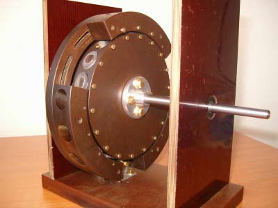 Photo – Perendeva Engine
 All of the inventions listed above are under development; modern scientists continue to improve them and look for the ideal option for developing a second-order perpetual motion machine.
In addition to the listed devices, the Alekseenko vortex engine, Bauman, Dudyshev and Stirling apparatuses are also popular among modern researchers.
How to assemble an engine yourself
Homemade products are in great demand on any electricians forum, so let's look at how you can assemble a magnetic motor-generator at home. The device that we propose to construct consists of 3 interconnected shafts, they are fastened in such a way that the shaft in the center is turned directly to the two side ones. Attached to the middle of the central shaft is a disk of lucite, four inches in diameter and half an inch thick. The outer shafts also feature two-inch diameter discs. There are small magnets on them, eight on the large disk and four on the small ones.
 Photo – Magnetic motor on suspension
 The axis on which the individual magnets are located is located in a plane parallel to the shafts. They are installed in such a way that the ends pass near the wheels with a flash per minute. If these wheels are moved by hand, the ends of the magnetic axis will be synchronized. To speed things up, it is recommended to install an aluminum block into the base of the system so that its end slightly touches the magnetic parts. After such manipulations, the structure should begin to rotate at a speed of half a revolution per second.
The drives are installed in a special way, with the help of which the shafts rotate similarly to each other. Naturally, if you influence the system with a third-party object, for example, a finger, it will stop. This perpetual magnetic engine was invented by Bauman, but he was unable to obtain a patent because... At that time, the device was classified as a non-patentable VD.
Chernyaev and Emelyanchikov did a lot to develop a modern version of such an engine.
 Photo - How a magnet works
 What are the advantages and disadvantages of actually working magnetic motors?
Advantages:
- Full autonomy, fuel economy, the ability to use available means to organize the engine in any desired place;
- A powerful device using neodymium magnets is capable of providing energy to a living space up to 10 VKt and above;
- The gravitational engine is capable of working until it is completely worn out and even at the last stage of work it can produce the maximum amount of energy.
Flaws:
- The magnetic field can negatively affect human health, especially the space (jet) engine is susceptible to this factor;
- Despite the positive results of the experiments, most models are not able to work under normal conditions;
- Even after purchasing a ready-made motor, it can be very difficult to connect it;
- If you decide to buy a magnetic pulse or piston motor, then be prepared for the fact that its price will be greatly inflated.
The operation of a magnetic motor is the pure truth and it is real, the main thing is to correctly calculate the power of the magnets.
Ecology of consumption. Science and technology: One option for a magnetic motor is a product called Radial Solenoid Engine. Its mode of operation is being tested.
This video shows a homemade Radial Solenoid Engine. This is a radial electromagnetic motor, its operation is tested in different modes. It is shown how the magnets are located, which are not glued, they are pressed with a disk and wrapped with electrical tape. But at high speeds, displacement still occurs and they tend to move away from the structure.
This test involves three coils that are connected in series. Battery voltage 12V. The position of the magnets is determined using a Hall sensor. We measure the current consumption of the coil using a multimeter.
Let's conduct a test to determine the number of revolutions on three coils. Rotation speed is approximately 3600 rpm. The circuit is assembled on a breadboard. Powered by a 12 volt battery, the circuit includes a stabilizer and two LEDs connected to a hall sensor. 2-channel hall sensor AH59, with one channel opening when the south and north poles of a magnet pass nearby. The LEDs blink periodically. Controlling powerful field effect transistor IRFP2907.
Hall sensor operation
There are two LEDs on the breadboard. Each is connected to its own sensor channel. The rotor has neodymium magnets. Their poles alternate according to the north-south-north pattern. The south and north poles alternately pass near the Hall sensor. The higher the rotor speed, the faster the LEDs blink.
The engine speed is controlled by a Hall sensor. The multimeter determines the current consumption on one of the coils by moving the Hall sensor. The number of revolutions changes. The higher the motor speed, the higher the current consumption.
Now all the coils are connected in series and participate in the test. The multimeter will also read the current consumption. Measuring the rotor speed showed a maximum of 7000 rpm. When all coils are connected, the start occurs smoothly and without external influence. When three coils are connected, you need to help with your hand. When braking the rotor by hand, the current consumption increases.
Six coils are connected. Three coils in one phase, three in another. The device removes current. Each phase is controlled by a field effect transistor.
Measuring the number of rotor revolutions. The starting currents have increased and the rated current has also increased. The engine reaches its rev limit faster at approximately 6,900 rpm. It is very difficult to brake the engine by hand.
The three coils are connected to 12 volt power. The other 3 coils are shorted by wire. The engine began to pick up speed more slowly. The device takes current consumption. The three coils are connected to 12 volt power. These three coils are closed by a wire. The rotor spins more slowly, but reaches maximum speed and works fine.
The multimeter takes the circuit current from three coils. Short circuit current. Four coils are connected in series. Their cores are parallel to the rotor magnets.
The device measures current consumption. It accelerates more slowly, but there is no sticking point with this coil arrangement. The rotor rotates freely. published
Electric motors are devices in which electrical energy is converted into mechanical energy. The principle of their operation is based on the phenomenon of electromagnetic induction.
However, the way the magnetic fields interact, causing the motor rotor to rotate, differ significantly depending on the type of supply voltage - alternating or direct.
The principle of operation of a DC electric motor is based on the effect of repulsion of like poles of permanent magnets and attraction of unlike poles. The priority of its invention belongs to the Russian engineer B. S. Jacobi. The first industrial model of a DC motor was created in 1838. Since then, its design has not undergone fundamental changes.
In low-power DC motors, one of the magnets is physically existing. It is attached directly to the machine body. The second is created in the armature winding after connecting a direct current source to it. For this purpose, a special device is used - a commutator-brush unit. The collector itself is a conductive ring attached to the motor shaft. The ends of the armature winding are connected to it.
In order for torque to occur, the poles of the permanent magnet of the armature must be continuously swapped. This should happen at the moment the pole crosses the so-called magnetic neutral. Structurally, this problem is solved by dividing the collector ring into sectors separated by dielectric plates. The ends of the armature windings are connected to them alternately.
To connect the collector to the power supply, so-called brushes are used - graphite rods with high electrical conductivity and a low coefficient of sliding friction.
The armature windings are not connected to the supply network, but are connected to the starting rheostat through a commutator-brush assembly. The process of turning on such a motor consists of connecting to the supply network and gradually reducing the active resistance in the armature circuit to zero. The electric motor turns on smoothly and without overload.
Features of using asynchronous motors in a single-phase circuit
 Despite the fact that the rotating magnetic field of the stator is easiest to obtain from a three-phase voltage, the operating principle of an asynchronous electric motor allows it to operate from a single-phase household network if some changes are made to their design.
To do this, the stator must have two windings, one of which is the “starting” winding. The current in it is shifted in phase by 90° due to the inclusion of a reactive load in the circuit. Most often for this
Almost complete synchronism of magnetic fields allows the engine to gain speed even with significant loads on the shaft, which is what is required for the operation of drills, rotary hammers, vacuum cleaners, grinders or floor polishers.
If an adjustable one is included in the supply circuit of such an engine, then its rotation frequency can be smoothly changed. But the direction, when powered from an alternating current circuit, can never be changed.
Such electric motors are capable of developing very high speeds, are compact and have greater torque. However, the presence of a commutator-brush assembly reduces their service life - graphite brushes wear out quite quickly at high speeds, especially if the commutator has mechanical damage.
Electric motors have the highest efficiency (more than 80%) of all devices created by man. Their invention at the end of the 19th century can be considered a qualitative leap in civilization, because without them it is impossible to imagine the life of a modern society based on high technology, and something more effective has not yet been invented.
Synchronous principle of operation of an electric motor on video


")


