The use of home automated systems can significantly save energy. For example, by installing a sensor on the street lighting on the approach to the house, in the entrance, hallway, or pantry, you will save yourself from the need to fumble for the switch in the dark and will never forget to turn it off. In this article we will talk about the features of sensors and how to make a motion sensor with your own hands.
Briefly about sensors
The motion sensor switches the load in the presence of external influence, which depends on the type of sensor and its operating principle. When the presence or movement of a body is detected, power is supplied to the load through a triac or electromagnetic relay. Anything can act as a load: a light bulb, a heater, a loudspeaker, as long as the load power does not exceed the maximum switching power of the sensor. Typically the maximum load power is about 1 kW.
If you need to turn on more power, you need to add another relay to the circuit so that the power terminals of the motion sensor turn on the voltage to the relay coil.
How the device works
The operating principle of the sensor depends on the type of connection diagram and the element used. Although their task is the same, their implementation methods are different. Motion sensors can be divided into groups according to the principle of their operation. Let's look at the advantages and disadvantages of each of them.
Contact or magnetic
The simplest option is to use a mechanical limit switch; with it you can turn on the light when the door is open or closed, for example. This is not exactly a sensor, but still, the simplest way to implement automatic switching on of devices.
The next option is a reed switch (sealed contact), its essence is as follows: in a glass bulb there is a pair of contacts that can close or open under the influence of a magnetic field. In this case, a permanent magnet is installed on the door, and a reed switch is located on the doorway (platband). Its contacts are often not capable of passing large currents, so they can be used to turn on the relay winding to increase the switching capacity.
Motion sensor circuitIR sensor
Infrared motion sensors respond to infrared radiation; this is radiation with a wavelength of 1± mm or a frequency of 300-400 GHz. The PIR sensor is used as the main sensitive element. It records changes in the amount of radiation on it.
IR radiation is thermal radiation.
This means that in the IR range a person looks like a large source of radiation. In this case, the temperature of the sensor itself does not significantly change its operation. Information from the outside world must reach the sensor, for this radiation is collected by a group of lenses, such as a Fresnel lens. Outwardly, it looks like a window in a casing with ribbed glass.
Depending on the design, the viewing angle of IR motion sensors can reach up to 360 degrees; in this case, several pyroelectric elements (PIR) are usually installed inside, and the lenses focus on them from the corresponding visibility zones. Such wide-angle sensors are needed to record movement from all sides, so as not to install several narrow-angle sensors; one is installed at 360 degrees on the ceiling.
 IR sensors react to heat
 Advantages:
- price;
- simplicity;
- prevalence;
- works well indoors;
- good adjustments;
- Does not irritate animals.
Flaws:
- unreliability;
- problems when working outside.
Since it reacts to heat, it has many “harmful” factors for precise operation. False alarms occur in response to any gust of warm wind or a switched-on heater, and the background temperature should differ (to a lesser extent) than the human temperature. Therefore, it is unlikely to work in the kitchen when you find yourself in front of a hot stove, but is it needed there?
Laser or photosensor
A laser sensor is a pair of elements, an emitter and a receiver, and the emitter can be in the IR spectrum so as to be undetectable by the human eye. Such sensors are used in alarms; when you cross a laser beam, it does not reach the photodetector (photoresistor or photodiode) and the circuit generates a signal about the presence in the room. How to use this signal depends on further connections; you can turn on the light through a time relay or siren or a signal to the security and safety system control unit.
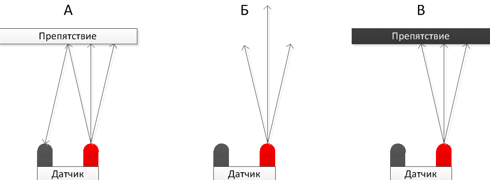
Another type of photo sensors looks like this: the LED emitter and receiver are not installed opposite each other, but nearby, in the same plane, the radiation is reflected and hits the optical receiver, when you enter the field of view of the sensor, the motion sensor is triggered. Another name is obstacle sensor.
Advantages:
- Simplicity.
Flaws:
- Narrow field of view.
- Specificity of application.
 Specifics of the action of the motion photo sensor
 Microwave
Microwave motion sensor - works on the principle of a radio receiver-transmitter. High-frequency oscillations are generated in the circuit and received here; the receiving part is configured in this way: when no one is nearby, the relay is turned off. When you enter the working area of the receiver, the oscillation frequency changes, as a result of which a signal is sent from the detector diode that you need to turn on the power element and apply voltage to the load.
Flaws:
- High-frequency radiation is harmful to health (although you carry a smartphone in your pocket, there is even more radiation there).
- Relatively high cost.
- False alarms are possible due to impacts outside the observed area.
Advantages:
- sensitivity allows you to detect an object behind a door or glass, for example;
- detects even the slightest movements.
 This is how a microwave motion sensor works
 Ultrasonic
Another type is built on the “emitter-receiver” principle – an ultrasonic motion sensor. The frequency of the ultrasonic wave lies in the range above 20 kHz but below 60 kHz. The detection principle is based on the Doppler effect. The length of the reflected wave changes, the receiver records this change and gives a signal about the presence and movement of a new object.
Flaws:
- Animals may react to it. Dog repellers use ultrasonic emitters.
- If you move slowly, the ultrasonic DD may not work.
Advantages:
- reasonable cost;
- insensitive to changes in environmental conditions.
Circuits for homemade motion sensors
We propose to consider several schemes suitable for repeating and studying the principles of operation of sensors. In addition, the microwave will also help you master the basics of radio transmission technology and signal detection, and circuits using microcontrollers will allow you to make a modular version with ready-made solutions for Arduino.
 Presence detector circuit
 Capacitive
Let's take the normal state to be when there is no one near the sensor, and the triggering state to be when you are nearby.
Transistor VT1 is a generator unit on a field switch configured at 100 kHz. The oscillatory circuit L2C2 is tuned into resonance with it. Electrically connected to the generator through R2. VD1 (detector diode). The frequencies are indicated in the absence of external influences, i.e. you do not touch the circuit and are removed from it. Part DA1 is a comparator, needed to compare the signal from the diode and the reference voltage specified through R3. In a normal state, the output should tend to zero. In this case, the signal at the non-inverting input of the comparator “–” is 5 V, and at the output – 0 V.
When you approach the sensor, the capacitance will increase, the frequency of the generator will decrease, you influence the frequency of the generator, and L2C2 the frequency is set by an oscillating circuit in parallel with the capacitance and inductance.
The resonance between the oscillator and this circuit disappears, and the voltage at the non-inverting input drops. Since the voltage at the inverter increases, the output begins to pull up to the supply voltage and stops at 8 volts (approximately), they can be used to control relays, through a transistor to amplify the output current, thyristors and other devices from which you are already powering the load.
Both coils are wound on ferrite rings 2000 NM, 20 mm with an outer diameter of 100 turns of PEV-2 wire 0.2 mm, turn to turn. In turn, L1 has a tap from the 20th turn, and L2 from the 50th turn (from the middle). Wind it so that the distance between the beginning and the end is no less than 0.3 mm.
Sensor – 2 pieces of wire 1 mm in diameter and 1–1.5 m long are located at a distance of 20 cm from each other.
Setting: we measure the voltage of C5 with a voltmeter, rotating the tuning C4, we achieve the maximum voltage (2.5–5 V), if the voltage is lower, we add a 15 pF constant capacitor in parallel with C3, if there is still not enough voltage, we reduce R1, but not less than 500 kOhm. The next step is to unscrew R3 to the bottom position according to the scheme, and R2 to the middle position. The LED connected to the op-amp output through a resistor lights up. Rotate R3 to make it go out. Carry out the settings directly where it will be installed. If you carry out the setup on the desktop, and then place the sensor where you planned, you will most likely have to configure it again.
Thermal sensor on Arduino
To build a PIR motion sensor project on Arduino you need:
- PIR sensor HC-SR501.
- Arduino UNO (or any other similar one).
- Power supply 4–6 V.
 Connecting sensor elements
 HC-SR501 – contains 1 pyroelectric element, it is covered with a lens, and the necessary wiring on a printed circuit board. Trimmer resistors are located on one side of the board to adjust sensitivity and delay time. The output signal has an amplitude of 3.3 volts, and the supply voltage is 5–12 volts. The maximum distance at which the sensor will operate is 7 m, and the time delay after activation is up to 5 minutes.
 Sensor connection diagram
 Connection diagram for controlling light via a relay.
 Light control
 Visual diagram of connections on a solderless breadboard
A motion sensor is most often used to turn on lights when you pass or are near them. With its help, you can save electricity and save yourself from having to flip the switch. This device is also used in alarm systems to detect unwanted intrusions. In addition, they can also be found on production lines, where they are needed to automatically perform any technological tasks. Motion sensors are sometimes called presence sensors.
Types of motion sensors
Motion sensors are distinguished by their operating principle; their operation, accuracy and features of use depend on this. Each of them has strengths and weaknesses. The final price of such a sensor also depends on the design and type of element used.
The motion sensor can be made in one housing or in different housings (the control unit is separate from the sensor).

Contact
The simplest motion sensor option is to use or. A reed switch (sealed contact) is a switch that is activated when a magnetic field appears. The essence of the work is to install a limit switch with normally open contacts or a reed switch on the door, when you open it and enter the room, the contacts will close, turn on the relay, and it will turn on the lighting. Such a diagram is shown below.

Infrared
They are triggered by thermal radiation and react to temperature changes. When you enter the field of view of such a sensor, it is triggered by thermal radiation from your body. The disadvantage of this detection method is false positives. Thermal radiation is inherent in everything that is around. Here are some examples:
1. stands in a room with an electric heater, which periodically turns on and off according to a timer or thermostat. When the heater is turned on, false alarms may occur. You can try to avoid this by taking a long time and carefully adjusting the sensitivity, as well as by trying to direct it so that there is no heater in the direct line of sight.
2. When installed outdoors, it may be triggered by gusts of warm wind.
Overall these sensors work fine and are the cheapest option. A PIR sensor is used as a sensitive element; it creates an electric field proportional to thermal radiation.
But the sensor itself does not have a wide directionality; a Fresnel lens is installed on top of it.

It would be more correct to say - a multi-segment lens, or a multilens. Pay attention to the window of such a sensor, it is divided into sections; these are lens segments; they focus the incoming radiation into a narrow beam and direct it to the sensitive area of the sensor. As a result, radiation beams from different directions fall on the small receiving window of the pyroelectric sensor.
To increase the efficiency of motion detection, dual or quad sensors or several separate ones can be installed. Thus, the field of view of the device expands.
Based on the above, it should also be noted that the sensor should not be exposed to light from the lamp, and there should be no incandescent lamps in its field of view, this is also a strong source of IR radiation, then the operation of the system as a whole will be unstable and unexpected. IR rays don't travel well through glass, so it won't work if you're walking behind a window or glass door.
This is the most common type of sensor; you can buy it or you can assemble it yourself, so let’s look at its design in detail.
How to assemble an IR motion sensor with your own hands?
The most common option is the HC-SR501. It can be bought at a radio parts store, on Aliexpress, and is often supplied in Arduino kits. Can be used in conjunction with a microcontroller or independently. It is a printed circuit board with a microcircuit, wiring and one PIR sensor. The latter is covered with a lens, there are two potentiometers on the board, one of them regulates the sensitivity, and the second is the time at which a signal is present at the output of the sensor. When motion is detected, a signal appears at the output and lasts for the set time.
It is powered by a voltage of 5 to 20 volts, operates at a distance of 3 to 7 meters, and the output signal lasts from 5 to 300 seconds, you can extend this period if you use a microcontroller or a time delay relay. The viewing angle is about 120 degrees.

The photo shows the sensor assembly (left), the lens (bottom right), and the reverse side of the board (top right).

Let's take a closer look at the board. There is a sensitive element on its front side. On the back there is a microcircuit, its wiring, on the right there are two trimming resistors, where the top one is the signal delay time, and the bottom one is the sensitivity. In the lower right part there is a jumper for switching between modes H and L. In mode L, the sensor produces an output signal only for the period of time set by the potentiometer. Mode H produces a signal while you are in the range of the sensor, and when you leave it, the signal will disappear after a time set by the upper potentiometer.

If you want to use a sensor without microcontrollers, then assemble this circuit, all elements are labeled. The circuit is powered through a quenching capacitor, the supply voltage is limited at 12V using a zener diode. When a positive signal appears at the sensor output, relay P is turned on through an NPN transistor (for example BC547, mje13001-9, KT815, KT817 and others). You can use a car relay or any other with a 12V coil.
If you need to implement some other functions, you can use it in conjunction with a microcontroller, for example. Below is the connection diagram and program code.


Ultrasonic
The emitter operates at high frequencies - from 20 kHz to 60 kHz. This leads to one problem - animals, such as dogs, are sensitive to these frequencies, moreover, they are used to scare them away and train them. Such sensors can irritate them and this causes problems.
The ultrasonic motion sensor operates on the Doppler effect. The emitted wave, reflected from a moving object, returns and is received by the receiver, while the wavelength (frequency) changes slightly. This is detected and the sensor produces a signal that is used to control a relay or triac and switch the load.
The sensor processes movements well, but if the movements are very slow, it may not work. The advantage is that they are not sensitive to changes in environmental conditions.
Laser or photo sensors
They have an emitter (for example, an IR LED) and a receiver (a photodiode of a similar spectrum). This is a simple sensor, it can be implemented in two versions:
1. The emitter and photodiode are mounted in the passage (controlled area) opposite each other. When you pass through it, you block the radiation and it does not reach the receiver, then the sensor is triggered and the relay is turned on. This can also be used in alarm systems.
2. The emitter and the photodiode are located next to each other, when you are in the range of the sensor, the radiation is reflected from you and hits the photodiode. This is also called an obstacle sensor and is successfully used in robotics.

Microwave
It also consists of a transmitter and receiver. The first generates a high-frequency signal, the second receives them. When you pass nearby, the frequency changes. The receiver is configured in such a way that when the frequency changes, the signal is amplified and transmitted to an actuator, such as a relay, and the load is turned on.
Microwave motion sensors are very sensitive, allowing you to “see” an object even behind a door or behind glass, but this also causes problems of false alarms when the object is outside the field of intended visibility.

These are quite expensive sensors, but they respond to even the smallest movements.
Capacitive devices work in a similar way. Such a diagram is shown below.

How to connect a motion sensor?
You can come up with countless options and schemes for connecting a motion sensor depending on your needs, sometimes you need the system to be triggered when moving in different places, for example, street lighting along the way from the house to the gate and vice versa, in other cases it is necessary to force the light to turn on or off, etc. .d. We will look at several options.
Typically a motion sensor has three wires or three terminals to connect to:
1. Coming phase.
2. Phase leaving to power the load.
If you do not have enough sensor power, use an intermediate relay and. To do this, instead of a light bulb in the circuits below, the coil terminals are connected.

The photo below shows the terminals to which the power wires are connected.

Conclusion
Using motion sensors is, as much as it sounds, a step. Firstly, it will help save energy and lamp life. Secondly, it will eliminate the need to flip the switch every time. For outdoor lighting, with the correct settings, you can make the light turn on when you approach the gate of the house.
If the distance from the gate to the house is 7-10, you can get by with one sensor, then you won’t have to lay a cable to the second sensor or assemble a circuit with a pass-through switch.
As already mentioned, IR sensors are the most common; they are sufficient for simple tasks; if you need greater sensitivity or accuracy, take a closer look at other types of sensors.
The so-called “Smart Home” system has become increasingly popular in everyday life, when in apartments, houses and entrances, to save electricity and increase living comfort, a special device is installed that controls the switching on of lights during live activity (presence and movement of a person) - a motion sensor. This useful device has already become a necessary component of modern security systems, but its high cost forces “craftsmen” to generate their own ideas, make analogues, having first carefully studied the principle of operation of the sensor and its types.
What types of motion sensors are there?
There are external sensors, which are usually installed on the streets, and internal ones, used indoors. The distance of the street device to the object allows you to understand how it works and select the optimal device for accurate response to movement.


If the distance is large, for example, a huge cottage or the area in front of an apartment building, then it is necessary to install a perimeter alarm that responds to activity up to a range of 500 meters.


What are the differences between motion devices?
The ultrasonic motion sensor remains one of the most popular on the market because it is inexpensive, very durable and wear-resistant. Its work is based on ultrasound, which is emitted when motion is detected.
The radio frequency sensor is also very famous, and it is much more expensive than the ultrasonic sensor, mainly because it can recognize movements in different ranges. Its operation is based on radar.


The most expensive, but very practical device is an infrared sensor. It is set to a certain temperature and turns on when exactly the owner of the required temperature indicators appears in the availability field, which eliminates unnecessary activation when a rat or other animal runs past.

How to do it yourself?
Assembling such a sensor is quite simple, but you still need to understand that the project has both positive and negative aspects during implementation.

On the positive side:
- incredible savings in resources and finances;
- no additional maintenance or wizard help required for setup;
- everything is calculated specifically for you and according to your living conditions or location;
- If everything is assembled correctly and the sensor works, you will save on electricity.
Negative points:
- It may not work out the first time, there will be a lot of trial and error;
- if you solder something incorrectly, you won’t be able to fix it; all you have to do is look for a new case and parts;
- Finding these parts is sometimes much more tedious than just going to the store and buying a finished product.

If you still want to assemble a motion sensor yourself, then start the process by searching for a diagram. For example, you can use the very simple diagram presented below:
The Doppler sensor is the easiest to manufacture, and you can make it using available materials.
You can make a device to turn on the light according to a different scheme. Great knowledge of physics and electronics is not required, and if you follow the instructions in this article, no difficulties will arise.
You will need:
- power supply with wires of different lengths;
- soldering iron;
- laser (sold at any home improvement store or FIX PRICE);
- screws and photodiodes;
- resistor (tuning);
- voltmeter;
- relay.

Once you have obtained all the necessary parts, you can begin assembly. It is necessary to strictly follow the plan.
- Cut off the connectors from the power supply, and then use a voltmeter to find the plus.
- Take a 10 kOhm resistor and solder it to the positive.
- Solder the cathode of the photodiode to the positive of the resistor itself, then solder the anode of the photodiode.
- Connect the emitter of transistor VT1 to the minus.
- Solder the VT2 emitter to the negative of the resistor.
- Solder the VT2 collector to the contact of the device for switching electrical circuits.
- Connect the second contact of the reed relay to the power supply. Use a laser pointer and attach a couple more wires to the power supply to save money.
- Now you will need a sealing plumbing gasket. You need to insert a screw into it so that its cap is inside the laser pointer.
- Attach one wire to the screw, and insert the second between the pointer body and the gasket.
- Make sure that all points are completed and everything is assembled correctly.
- Turn on the device to test and work on errors, if any are found.

Now you have your own device that reacts to light, made yourself. You can also try making a motion sensor for an alarm. You will have your own security system, which will not take much time to assemble.
An infrared sensor is ideal for this, and making it will not be difficult. It is absolutely safe for both humans and animals, and is reliable in operation.
Need to get:
- reed field;
- wires (supply);
- photodiode;
- frame;
- n-p-n transistor;
- resistor (tuning).


When all the parts are found, we do the installation. Our resistor will regulate the sensitivity, and the functions of the comparing relays will be performed by a zener diode. Let's prepare the antenna. To prevent oxidation, you need to polish it and rub it with acetone. Wrap the coils with wires, fix the sleeve in the central opening.
Place the made device in a prepared case (you can take an old one from a household appliance), just make holes first in order to secure the structure and for better visibility of the LEDs. Then attach the fluorescent lamp.
You need to be extremely careful when making holes so that they are not too large.

How to adjust sensitivity correctly?
The sensor and photo relay have the same connection principle. If you look closely you will see 3 terminals and 3 wires. The wires of the sensor itself are supplied with 220 volts, which is equal to zero, and the incoming phase. The third wire goes to the phase of the lamp; it is to this phase that 220 volts will be supplied from the distribution box.
If you want to turn on the light yourself, you can install a switch between the incoming and outgoing phases. This switch will bypass the sensor if necessary. If you need to forcefully turn off the light, then the switch is placed in the gap before the sensor for the incoming phase.

If the device works properly, you can install it in the planned place and reap the fruits of your labor with pride. Now you can save a lot on electricity bills and be the owner of a homemade security system. Of course, you can always purchase a ready-made device at an electrical goods store, and the cost will not break your wallet, since it fluctuates around 600 rubles, but it is much more pleasant to make a thing at home and be 100% sure of every detail.
To learn how to create a motion sensor with your own hands, see below.
What are pyromodules? How to enable and use them correctly? This article will answer all these questions.
The creation and installation of pyromodules in this article will be discussed using the example of modernizing the EK-0.3 coffee maker.
As you know, this type of coffee maker does not have the function of turning off after making coffee. Very often such devices suffer a sad fate, because they can explode because they lack automation. Therefore, in order for the operation of the device to be safe and its “life” to be long, it is necessary to take certain measures.
One option is to use a special thermal switch that will turn off the coffee maker. The disadvantage of this method is that the switch will only operate when the case temperature is above 120 degrees. And at this temperature, there is usually no water in the coffee maker’s reservoir completely. As a result, all this will lead to the body of the coffee maker overheating, and the amount of energy required will increase several times. The best option is to use a motion sensor; it will independently track the moment coffee is poured into the coffee pot.
PIR (motion) Sensor (pyromodule) - what is it?
This abbreviation stands for as follows:
– PIR– Passive Infra-Red;
– FEAST– Passive Infrared.
So what is it? This device converts infrared radiation (more precisely, a change in its intensity) into electric current. In certain crystalline rock materials, if the temperature is changed, a pyrostatic effect occurs. It is on this effect that the operation of the pyromodule is based. The temperature in materials changes precisely due to infrared radiation.
The electric field needs to be registered, but to do this it needs to change. And when changing, the crystalline dielectrics will be compensated by free electric charges. All sensors built using pyroelectrics have this property. This means that they will all be able to track even the slightest change in radiation intensity. In this case, the pyromodule itself (its temperature) will not have any effect on the measurement results.
To protect the pyro-sensor from various negative influences and various interferences, it is necessary to enclose it in a sealed metal case. The housing must have a window that allows light to pass through (narrow radiation range). In order for light to pass through in this range, the window must be covered with an infrared cut-off filter. The spectral characteristic of the filter is 10 µm (1*104 nm).
Design of an imported pyromodule:
– in addition to the pyro-sensor itself, a special amplifier is also located behind the infrared filter. It operates on a unipolar low-noise transistor. The diagram above shows how to turn on the “PIR D203S” pyromodule (foreign production), as well as its pinout.
In order to connect Soviet pyromodules, you will need to install a field-effect transistor. The diagram above shows how to turn on “PM-4” (Soviet production), as well as its pinout.
Previously, pyromodules were secretly developed in military-industrial complexes. They were installed in missiles and other similar devices, and were part of Thermal Homing Heads or TGS.
Today, the use of modules in civil engineering is widespread. The most common area is motion detectors in alarm systems and lighting control systems. The picture above shows an example, a Feron LX20/SEN5 sensor, which is intended for a lighting control system.
What results should be achieved when improving a coffee maker?
- The coffee maker should turn off the power as soon as coffee starts flowing into the pot. The process will be completed without electricity; the thermal energy accumulated by the housing will be sufficient to complete it.
- The coffee maker should switch off abnormally when the temperature exceeds 120 degrees. Otherwise, it will burn out due to lack of water.
This figure shows a block diagram. The motion sensor sends signals to the control unit. The control unit, in turn, can turn off the electromagnetic relay at the right time. And thanks to an electromagnetic relay, the entire coffee maker turns off at the right moment.
This diagram shows the control unit in its electrical version. Elements of the circuit and their purpose:
- PM-4– this is a pyromodule without a built-in amplifier;
- VT1– with its help, the pyromodule signal is amplified;
- DA1-1-DA1-2– adjusts the amplification of the pyromodule signal;
- VD1– a temperature sensor based on a germanium diode;
- DA1-3– amplifies the signal from the temperature sensor;
- DA1-4– stabilizes the virtual earth;
- VS1– blocks relay P1 and its power supply. Is a threshold element;
- VT2– this relay performs a delay at certain moments. For example, it prevents the coffee maker from switching off during transition processes while power is already supplied;
- Z1– stabilizes the voltage at 12 Volts;
- Z2– stabilizes the voltage at 8 Volts.
Construction and its details.
The picture shows a printed circuit board on which all the parts are assembled, with the exception of the temperature sensor. Board dimensions – 45x85mm.
Here is the board directly assembled.
As already mentioned, the temperature sensor is made using a germanium diode. The sensor mount is made of tin can.
The sensor is attached to the body of the coffee maker; silicone sealant is suitable for more reliable fastening. You can also apply a drop of KPT-8 thermal paste between the case and the bracket. The MGTF wire is used to connect the sensor (fluoroplastic insulation).
You need to drill two holes in the coffee maker stand.
These holes are needed to carry five wires. Two wires are needed for power, one wire will control the load and two more from the temperature sensor. The control unit is made in such a way that it is suitable for repair at any time.
The pyromodule eye must be protected. A polypropylene plate is perfect for this purpose. Such a plate can be taken in a disposable syringe, cut off from the piston. The pyromodule operates in a rather narrow spectrum of infrared radiation. This spectrum can be blocked by simple glass, but polypropylene will transmit it.
Additional materials.
Repair of transformers with welded cores. A simple scheme for controlling radio and electrical devices via Com ports
A fairly common practice is sound and motion sensors in the house. We suggest you consider how to make motion sensors with your own hands, instructions, diagrams and photos in our article.
How the device works
The operation of the device is based on the reception and transmission of impulses emanating from the vibration of air (or water, for example, in swimming pools) while moving (and it does not matter whether it is a car, a person or an animal). The functionality of the device may vary depending on the requirements for it. There are several types of motion sensors:
- thermal (react to temperature changes in the reachable field). The most striking example is an infrared or laser sensor, mainly used in security systems;
- sound (transmit and receive impulse when air vibrates from sounds). A very simple device, used to record movement in open space;
- oscillatory (respond to environmental fluctuations and changes in the magnetic field when moving within reach). They are most often used in an apartment or house to turn on or off lights, sound, and other things.
How to make a sensor
Let's look at how the most common motion sensor for alarm is created. It is done based on this scheme
 Motion sensor circuit
 You need to prepare the following tools and parts:
- voluminous body (can be taken from an old camera);
- Soviet-style control element base (buy at any electrical goods store or at a flea market);
- soldering machine;
- wires;
- screws;
- screwdriver;
Step by step guide
An autodyne is assembled on the basis of a transistor, which has now become a local oscillator and a mixing device for signaling. As soon as air vibrations (movement) are detected in the field protected by the device, the signal level will change. It fully corresponds to the Doppler shift, and will be equal to several hertz.
Video: how to make a motion sensor with your own hands
Next, with the help of a capacitor (in the diagram C2) and a low-pass filter (shown as C1, L3, the pulse will be sent to the alarm contact, which will also be a filtering part. Thanks to this, the pulse will reach its maximum and maintain these parameters for a certain time. Resistor (on Figure R11) will adjust the sensitivity of the circuit.
The comparators in this case are VD3 - a zener diode and a small relay (K1). It is imperative to take into account that the nominal mains voltage is 11 volts. Because of this, we also recommend connecting a signal-boosting stabilizer to the circuit.
Step two: adjust the board to the required parameters
There is an antenna at the top of our board; it needs to be thoroughly polished and treated with degreasing solutions; it is very advisable to cover it with rosin or at least acetone, because there is a high probability of oxidation of the antenna material during its use.
Next you need to wrap coil L1 and coil L2 with twelve turns of small-section wire (we took PEL-0.23).
Using a screw with a diameter of 3, screw the bushing to the central hole of the future sensor, secure it, and check the strength of the connection.
Now let's start fitting our body. We measure it, we need the board to fit into the box freely, i.e. the body is either sawn or another one is selected. In it we mark the location of the center of the board and there we also drill a similar hole, as in the diagram, treat it with acetone, and try on the board.
Three millimeters need to be drilled into the corners of the housing where the electrical circuit is installed. Some deviation is allowed depending on your mounting screws.
The screws, sleeve and plates can be of any material, but be sure to check that the holes and legs are even. In some cases, you will still need to drill holes for future LEDs, but basically they are visible through the body.
The simplest sensor is ready, when assembled it will look something like this. The installation is carried out according to a clear scheme: we connect a room lamp or a fluorescent lamp to the detector.
 Motion Sensor
 How to make a laser motion sensor
In the movies, everyone has seen lasers that signal the entry of robbers into a bank. Making an electronic motion sensor with your own hands using a laser is also not as difficult as it seems. You need to prepare the following components:
- infrared diode or photodiode, depending on capabilities and requirements;
- capacitive relay type RES55A,
- wire diagram;
- transistor and resistor blocks;
- 5 volt charger;
- multimeter;
- other tools and parts (gasket, screws, soldering iron).
First, let's disassemble the charger. We expose the wires and find positive and negative contacts there. Next, according to the rules, we need to set our resistor to minus. Now we connect a diode to it using a cathode, and the anode must be soldered to the adjustment resistor. Next, we solder the transistor emitter to the negative wire and connect a resistor to the base circuit.
In total, we get: resistor - minus, contactor - to the relay, relay - signaling device. The schematic diagram of an infrared sensor looks something like this:
 Schematic diagram of a motion sensor
 Using a screw, you need to attach this entire structure to the gasket, and connect the power wire to the screw head. Important: install the connecting screw so that it rests against the spacer spring; in this circuit it is a sensitive part.
This light alarm can be installed anywhere as long as there is an outlet nearby. It is most logical to place it at foot level.
Any of the above options can be customized to suit individual needs.
- The webcam itself can act as a motion indicator. If you connect it to the alarm, it will even make sounds, but in most cases it is enough to just download a special program to your computer;
- When connecting the sensor to the lighting system, make sure that there are no fans or large household appliances within its reach;
- To create a “smart home” with your own hands, we recommend using a touch switch. The fact is that in most cases there is already a built-in motion sensor;
- Select diodes for your laser carefully. IR radiation can be harmful to the eyes, so it is not recommended for domestic use;
- Car alarms are made using a similar principle. Only an audible alarm is also attached to the circuit diagram. When the sensor detects movement, a light comes on and a tone sounds, similar to a metal detector. Such a device is also called a radar sensor;
- If desired, include a capacitive display in the circuit; it will display the “Work” and “Stop” indicators. Or connect the monitor to a circuit similar to a webcam, and get a full-fledged home video surveillance network;
- It is quite possible to make a GSM alarm on a regular phone; to do this, you just need to download the program, just like on a PC.
If you need to carry out repairs, then all the indicators can be disassembled very quickly and basically the problem lies in the contacts, just clean them.
When you simply don’t have time to make motion sensors yourself, you can buy them at any electrical store; there are good reviews about the GrandWay and Siemens models. The average price of the device is 500 rubles.


